
Oscillator circuit structure

A circuit structure and oscillator technology, applied in the field of CMOS integrated circuits and integrated circuits, can solve the problems of increasing the manufacturing and packaging costs of CMOS integrated circuits, strict requirements on oscillation frequency, and increasing the total cost of peripheral components, etc., so as to improve market competitiveness , low cost and simple structure

Inactive Publication Date: 2013-07-03
CRM ICBG (WUXI) CO LTD
View PDF3 Cites 6 Cited by
  • Summary
  • Abstract
  • Description
  • Claims
  • Application Information

AI Technical Summary

Problems solved by technology

[0002] At present, the built-in oscillators of CMOS integrated circuits mostly adopt a simple circuit structure, and the time constant of charging and discharging of resistors and capacitors is used as the timing of the oscillation cycle. Since the value of the resistors and capacitors inside the CMOS integrated circuit will change with voltage and temperature, the oscillation frequency will change with the power supply voltage. , the ambient temperature changes, such a built-in oscillator cannot be used in circuits that have strict requirements on the oscillation frequency, for example, the national standard requires ±2% of the code sending frequency of the infrared remote control, and the built-in oscillator with a simple structure can The frequency deviation in the full temperature range of the voltage is much higher than ±2%, even up to 20%, which is far from meeting the requirements. In such a solution, only an external quartz crystal resonator or ceramic resonator can be used to generate an accurate clock. Such a solution not only increases the total cost of peripheral components, but also increases the manufacturing and packaging costs of CMOS integrated circuits, reducing the market competitiveness of products

Method used


Image

  • Oscillator circuit structure
  • Oscillator circuit structure
  • Oscillator circuit structure

Examples


Embodiment Construction

[0023] In order to understand the technical content of the present invention more clearly, the following examples are given in detail.

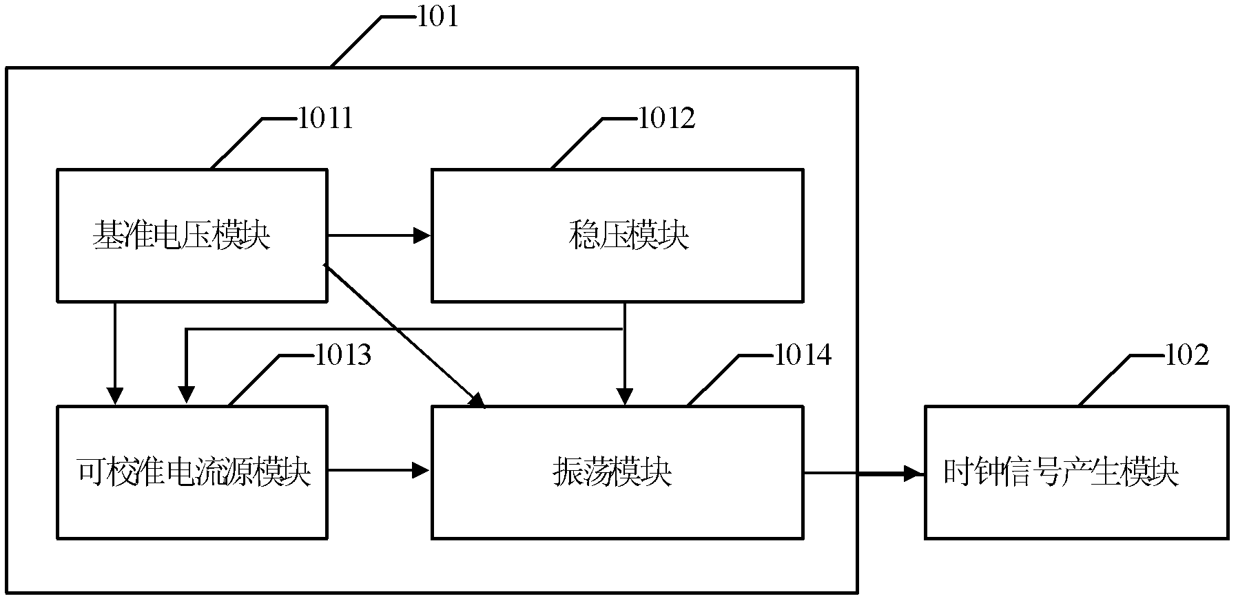
[0024] see figure 1 Shown is a structural schematic diagram of the oscillator circuit structure of the present invention.

[0025]In one embodiment, the oscillator circuit structure 101 includes a reference voltage module 1011, a voltage stabilizing module 1012, a calibratable current source module 1013, and an oscillation module 1014, and the reference voltage module 1011 is connected to the voltage stabilizing module 1012 , a calibratable current source module 1013 and an oscillating module 1014 for providing a reference voltage; the voltage stabilizing module 1012 is connected to the calibratable current source module 1013 and the oscillating module 1014 for providing a working power supply voltage; The calibratable current source module 1013 is connected to the oscillating module 1014 to provide a charging current source for the oscillat...


PUM


Abstract

The invention relates to an oscillator circuit structure which comprises a reference voltage module, a voltage stabilization module, a calibrated current source module and an oscillation module. The reference voltage module provides reference voltage for the voltage stabilization module, the calibrated current source module and the oscillation module; the voltage stabilization module provides working power source voltage for the calibrated current source module and the oscillation module; and the calibrated current source module provides a charge current source for the oscillation module. The oscillator circuit structure effectively reduces influence of changes of the power source voltage and environment temperature on frequency of an oscillator which is built in a complementary metal-oxide-semiconductor transistor (CMOS) integrated circuit so as to utilize the influence to provide a high-precision and high-stability clock for circuit working without needing to be externally connected with a quartz crystal resonator or a ceramic resonator, removes cost of a peripheral cell, reduces manufacturing and packaging cost of the COMOS integrated circuit, improves market competitiveness of a product, and is simple in structure, low in cost and wide in application range.

Description

technical field [0001] The invention relates to the technical field of integrated circuits, in particular to the technical field of CMOS integrated circuits, in particular to an oscillator circuit structure. Background technique [0002] At present, the built-in oscillators of CMOS integrated circuits mostly adopt a simple circuit structure, and the time constant of charging and discharging of resistors and capacitors is used as the timing of the oscillation cycle. Since the value of the resistors and capacitors inside the CMOS integrated circuit will change with voltage and temperature, the oscillation frequency will change with the power supply voltage. , the ambient temperature changes, such a built-in oscillator cannot be used in circuits that have strict requirements on the oscillation frequency, for example, the national standard requires ±2% of the code sending frequency of the infrared remote control, and the built-in oscillator with a simple structure can The freque...

Claims


Application Information

Patent Timeline
IPC IPC(8): H03B5/04
Inventor 曹旺徐佰新赵海王效
Owner CRM ICBG (WUXI) CO LTD
Learn More