
Light-emitting diode (LED) healthy eye protection lamp

A technology for LED lamps and lamps, which is applied to lighting devices, light sources, and components of lighting devices, etc., can solve the problems of a large amount of gushing, increased human eye damage, and the uniformity of light emission cannot be compared with gas light-emitting lamps, so as to achieve a soft lighting effect. , Guaranteed luminous efficiency, beneficial to the effect of vision health

Inactive Publication Date: 2013-06-26
TIANJIN SICHI TECH DEV
View PDF6 Cites 0 Cited by
  • Summary
  • Abstract
  • Description
  • Claims
  • Application Information

AI Technical Summary

Problems solved by technology

[0005] The mechanism of blue light generation in LED is that the wavelength of blue light emitted by the blue light chip is concentrated at 450-455NM, and the blue light of LED is in the most harmful section. Yellow phosphor or red and green phosphor are used in LED, and phosphor attenuation may occur during the manufacturing process. (or the amount of fluorescent powder is small and the reflection is not enough), the original blue light emitted by the chip will flood out in large quantities, which will greatly increase the damage to human eyes
[0006] In addition, when LEDs are made into lamps, many LEDs will be installed on the heat dissipation substrate, and multiple LEDs will emit light at the same time to achieve lighting effects, but the LED itself has a very strong light direction, even if the number of LEDs is increased, the lens is placed, and the optics is optimized. Design and other measures cannot eliminate its "spot light" feature, which will make it incomparable with the current gas luminous lamps in terms of luminous uniformity

Method used


Image

  • Light-emitting diode (LED) healthy eye protection lamp
  • Light-emitting diode (LED) healthy eye protection lamp
  • Light-emitting diode (LED) healthy eye protection lamp

Examples


Embodiment Construction

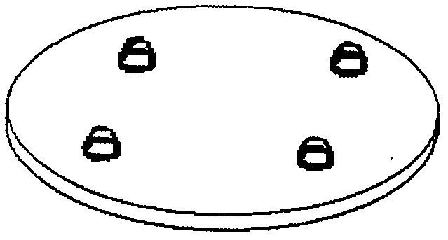
[0020] 1. Select the green LED as the light-emitting material, weld it on the heat dissipation base plate, and make the attached Figure 4 Bottom plate 1 in .

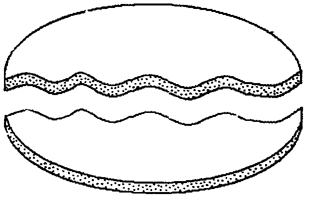
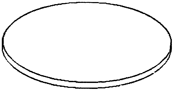
[0021] 2. Preparation of shading cover: Method 1 is to apply the prepared purple-red fluorescent substance on the surface of the shading plate to make an attached image 3 The shade shown; the second method is to mix the prepared fluorescent substance with the raw materials for preparing the shade, and then shape them together to form an attached figure 2 Hood shown.

[0022] 3. If the shape of the lamp and the heat dissipation allow it, attach Figure 4 The bottom plate 1 is shown assembled with a light shield 4 . The original green light 3 with strong directionality emitted by the green LED light emitting device 2 is converted into uniform and soft near-natural light 5 by the shade 4 .

[0023] 4. The shading cover 4 is installed on the lamp by using the slide rail slot, and is movable and replaceable, so that u...


PUM


Abstract

The invention provides a light-emitting diode (LED) healthy eye protection lamp, and relates to the fields of LED lamp manufacturing, application of luminescent materials and the like. The LED healthy eye protection lamp can enable the damage of an LED lamp to the vision of a person to be reduced substantially, maintains appropriate color temperature at the same time when luminous efficiency is improved, and reduces ultraviolet or blue light constituents which have great harm to the vision of the person. In particular, a green luminous LED is used as raw luminescent materials to be manufactured into the lamp, a light shield which is coated or mixed with amaranth fluorescent powder is added to the front of the lamp, and green light illuminates fluorescent materials on the light shield so that the purpose that ultimate emergent light is natural white light with a low color temperature can be achieved. The LED healthy eye protection lamp is used so that harmful blue light can not increase along with the fact that the fluorescent powder loses effectiveness slowly, and thereby harmful optical radiation can be reduced substantially, and meanwhile, an original similar point luminescent mode tends to be a face luminescent mode. By means of the LED healthy eye protection lamp, an improved LED desk lamp saves energy and prolongs the service life, and simultaneously protects the vision of users.

Description

technical field [0001] The invention relates to the technical fields of LED lighting, LED lamp manufacturing, luminescent materials and phosphor powder application, etc. Specifically, green LEDs that emit monochromatic light are made into lamps, and light-shielding materials coated or mixed with purple-red phosphor powder are added to the front of the lamps. The cover is used to achieve the purpose of the final emitted light being white light with a lower color temperature. The technical highlight of the present invention is that the green LED light-emitting device that does not contain blue light or ultraviolet components is used to irradiate the surface of the hood with a purple fluorescent substance that is coated or mixed with purple, and the illumination source that is close to natural light is excited and synthesized, so that the blue light or ultraviolet light that is harmful to eyesight The light radiation will not increase with the increase of the use time, and at the...

Claims


Application Information

Patent Timeline
Patent Type & Authority Applications(China)
IPC IPC(8): F21V9/10F21Y101/02F21V9/40F21Y115/10
Inventor 罗金荣牛晓芳
Owner TIANJIN SICHI TECH DEV
Learn More