Light-emitting diode (LED) lighting plate
A technology of light-emitting boards and LED lamp beads, which is applied to semiconductor devices, light sources, and shading of light-emitting elements, which can solve problems such as high cost, complicated processing, and inconvenient maintenance, and achieve good consistency, consistent pattern arrangement, and maintenance convenient effect
- Summary
- Abstract
- Description
- Claims
- Application Information
AI Technical Summary
Problems solved by technology
Method used
Image

Examples
Embodiment 1
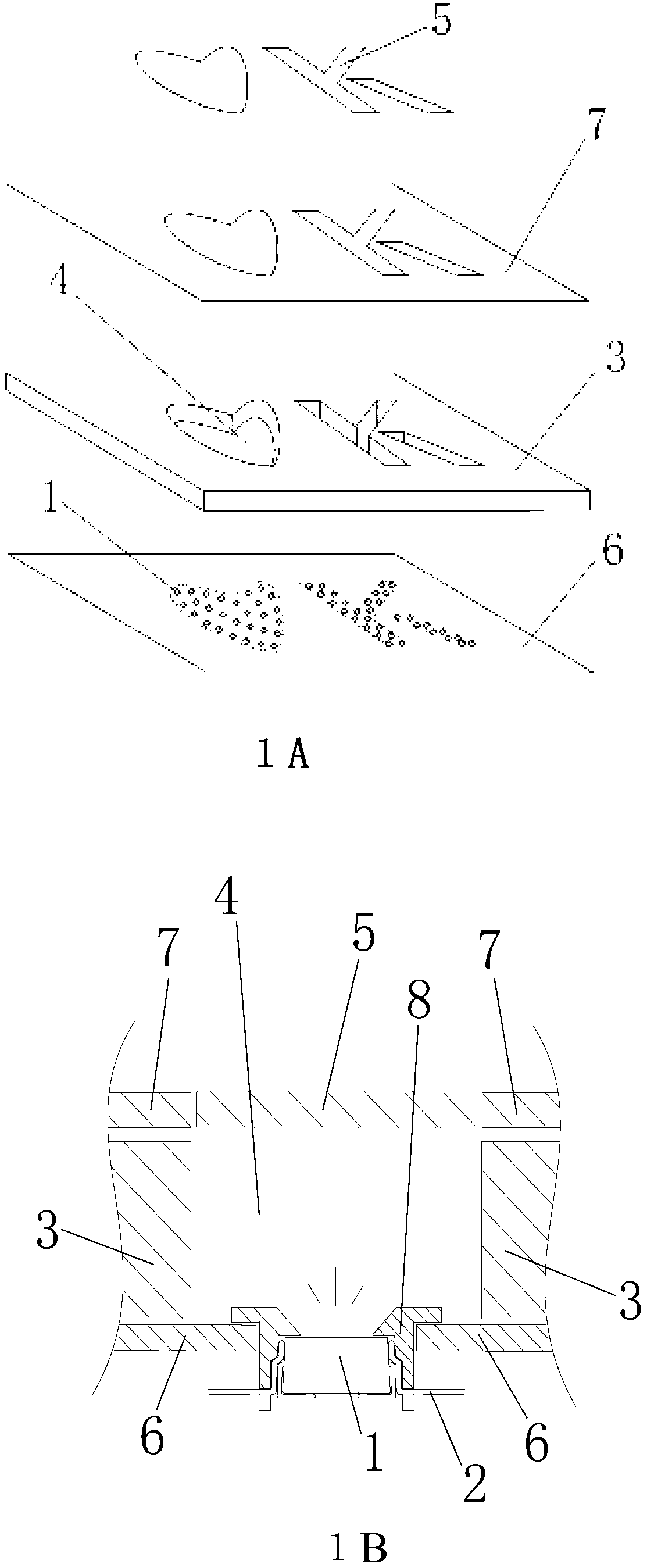
[0031] like figure 1 First, according to the luminous pattern (the light pattern drawing designed in the graphic design stage), the light-transmitting layer (5) corresponding to the design pattern is cut and engraved on the plate with astigmatism and uniform light effect respectively, and the hollow plate (3) ), cut out the hollow light-emitting cavity (4) corresponding to the design pattern, and cut out the hollow pattern consistent with the pattern of the light-transmitting layer (5) on the panel (7), and embed the light-transmitting layer (5) in the panel. (7) in the hollow pattern, and then on the bottom plate (6) according to the shape and area of the light-emitting cavity (4) according to the shape and area of the light-emitting cavity (4) according to a certain distribution density to make a number of holes for fixing the LED lamp bead holder (8), and then put a number of holes. The LED lamp beads (1) with electrical connection are fixed in the card holder (8) as th...
Embodiment 2
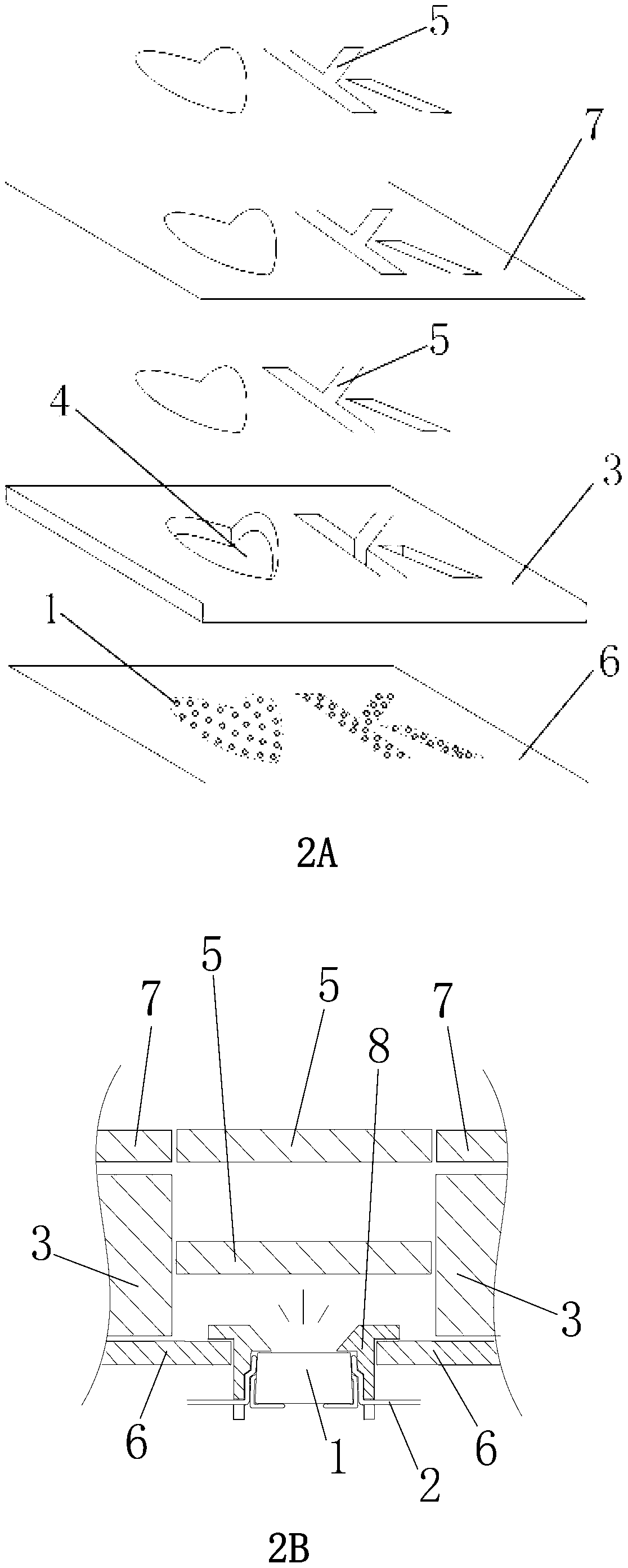
[0034] like image 3 First, according to the luminous pattern (the light pattern drawing designed in the graphic design stage), the light-transmitting layer (5) corresponding to the design pattern is cut and engraved on the plate with astigmatism and uniform light effect respectively, and the hollow plate (3) ), cut out the hollow light-emitting cavity (4) corresponding to the design pattern, insert the light-transmitting layer (5) into the upper end of the light-emitting cavity (4) on the hollow plate (3) and fix it, and then install it on the bottom plate (6). ) according to the shape and area of the light-emitting cavity (4) according to a certain distribution density to make a number of holes for the card holder (8) for fixing the LED lamp beads, and then insert the card holder (8) into the hole, and then put some electrical The connected LED lamp beads (1) are fixed in the card holder (8) as the light source of the light emitting cavity (4), and then all the LED lamp be...
Embodiment 3
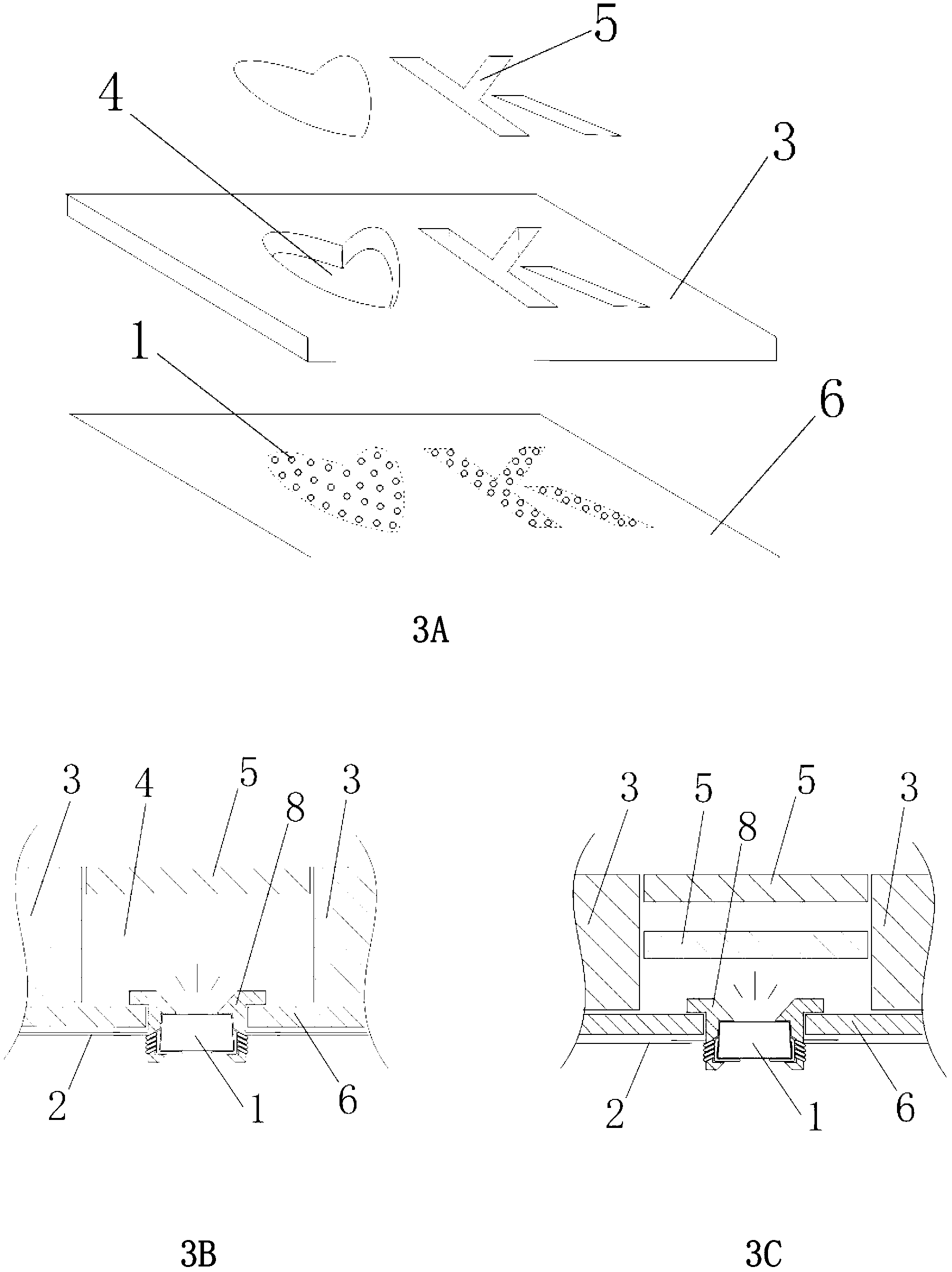
[0037] like Figure 4 As shown, in some specific environments, due to the limitation of objective conditions, the shape of the light-emitting cavity (4) cannot or is not necessary to be consistent with the surface light-transmitting layer (5) (light-emitting pattern), and some light-emitting patterns or The light-transmitting layers (5) corresponding to several independent light-emitting patterns are sealed on a light-emitting cavity (4), and the distribution density of the LED lamp beads (1) is properly adjusted, so that the light-emitting effect can be bright and uniform. Specific implementation can refer to embodiment 1.
PUM
 Abstract
Description
Claims
Application Information
 - R&D
- Intellectual Property
- Life Sciences
- Materials
- Tech Scout
- Unparalleled Data Quality
- Higher Quality Content
- 60% Fewer Hallucinations
Browse by: Latest US Patents, China's latest patents, Technical Efficacy Thesaurus, Application Domain, Technology Topic, Popular Technical Reports.
© 2025 PatSnap. All rights reserved.Legal|Privacy policy|Modern Slavery Act Transparency Statement|Sitemap|About US| Contact US: help@patsnap.com