
Rock reamer

A reamer and rock technology, applied in drilling equipment, earthwork drilling, drill bits, etc., can solve problems such as large rotational torque, accidents in the hole, drill pipe fracture, etc., to reduce rotational torque, reduce tool weight, and enhance use The effect of longevity

Inactive Publication Date: 2015-04-15
天津博为中天钻具有限公司
View PDF7 Cites 0 Cited by
  • Summary
  • Abstract
  • Description
  • Claims
  • Application Information

AI Technical Summary

Problems solved by technology

[0003] One is the oil-used cone palm welding structure. The problems with this structure are: 1. Too high temperature during welding will damage the seal of the cone bearing; 2. The replacement efficiency is low, and the scrapped cone needs to be cut off and welded again. It usually takes a day or two for a new cone; 3. The back of the palm of the cone is easy to wear, and the seal will wear through to a certain extent, causing the cone to fail, and even cause the cone to fall into the hole, causing the hole internal accident
[0005] However, when the above two reamers are used in the reaming process of large-scale pipelines passing through rocks, for example, after the reaming diameter of pipelines above 711 exceeds 800MM, there are the following problems in use: the reamer plus the matching centralizer are very heavy, and the drilling tool jumps Large, the rotation torque is also very large, when it exceeds the bearing range of the drill pipe, it will cause a large number of drill pipes to break, it is very difficult to handle, and even the drilling will be scrapped
When cutting at the same time, the rock particles are large, which is inconvenient to carry the mud, and the rock slag accumulates in the hole, making it difficult to ream and manage

Method used


Image

  • Rock reamer
  • Rock reamer
  • Rock reamer

Examples


Embodiment Construction

[0028] Below in conjunction with accompanying drawing and specific embodiment the present invention will be described in further detail:

[0029] In the following description, many specific details are set forth in order to fully understand the present invention, but the present invention can also be implemented in other ways different from those described here, therefore, the present invention is not limited to the specific embodiments disclosed below limit.

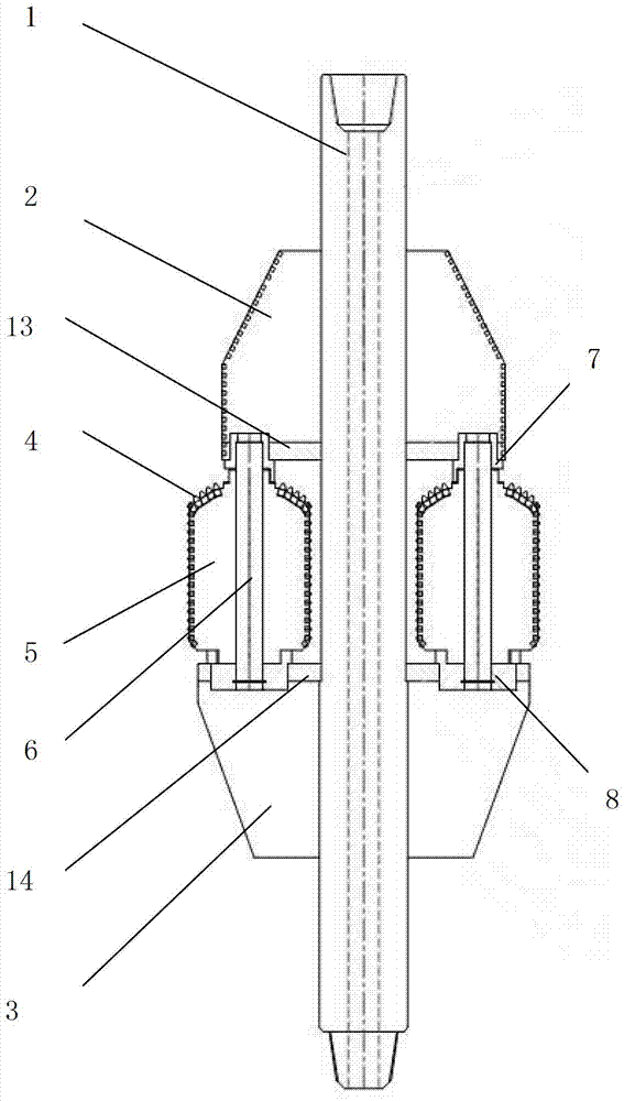
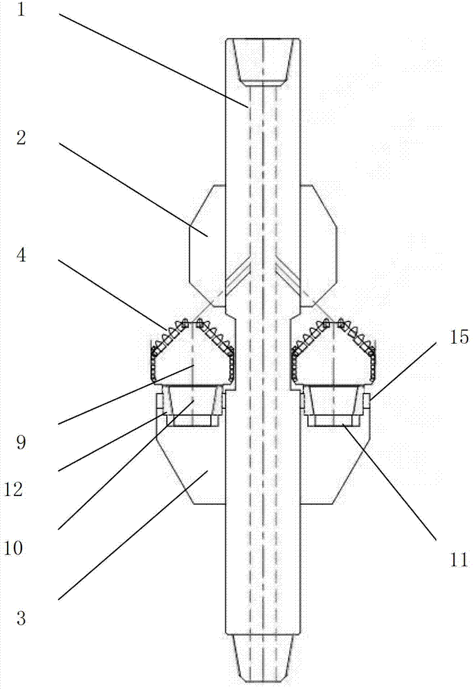
[0030] figure 1 and figure 2 One embodiment of the invention is shown. As shown in the figure, the reamer includes a hollow central shaft 1 whose two ends communicate with the drill rod, a front guide 2 , a rear guide 3 and a cylindrical hob 5 . The central axis 1 is provided with at least three said front guides 2 and at least three said rear guides 3 in the circumferential direction, and the three said front guides 2 and rear guides 3 are uniformly arranged in the circumferential direction, and said front guides 2...


PUM


Abstract

The invention discloses a rock reamer. The rock reamer comprises a hollow central shaft which is connected with a drill rod, a front pilot and a back pilot which are fixedly arranged on the hollow central shaft, and a hobbing cutter which can conduct autorotation and is arranged between the front pilot and the back pilot. A central axis of the hobbing cutter and the central shaft are parallelly arranged, the hobbing cutter comprises a cylindrical section which has a righting function and a front end face formed at the front end of the cylindrical section, and hard alloy teeth used for crushing rocks are evenly distributed on the front end face and the peripheral surface of the cylindrical section. By improving a hobbing cutter structure and arranging positions, the phenomenon that a matched righting machine is additionally arranged on a reamer is effectively avoided, weight of tool is reduced, rotation torsion moment is reduced, cost is lowered, and service life of the tool is prolonged. In addition, the hobbing cutter is clamped or connected between the front pilot and the back pilot in a threaded mode, and therefore disassembly of the hobbing cutter is convenient.

Description

technical field [0001] The invention relates to the field of rock crossing engineering construction, in particular to a rock reamer. Background technique [0002] At present, in the field of rock crossing engineering and the process of reaming in mines, water wells, and oil wells, rocks are often encountered. Each construction unit or drilling tool manufacturer adopts two methods of reaming: [0003] One is the oil-used cone palm welding structure. The problems with this structure are: 1. Too high temperature during welding will damage the seal of the cone bearing; 2. The replacement efficiency is low, and the scrapped cone needs to be cut off and welded again. It usually takes a day or two for a new cone; 3. The back of the palm of the cone is easy to wear, and the seal will wear through to a certain extent, causing the cone to fail, and even cause the cone to fall into the hole, causing the hole internal accident. [0004] The second type is a replaceable hob-type rock r...

Claims


Application Information

Patent Timeline
Patent Type & Authority Patents(China)
IPC IPC(8): E21B10/26E21B10/633E21B10/46
Inventor 佟功喜
Owner 天津博为中天钻具有限公司
Learn More