
Multiple ozone generating device

A technology for ozone generation and equipment, applied in the fields of electronics, electrochemistry, energy conservation and environmental protection, to achieve the effects of increasing ozone gas production rate, reducing raw material costs and operating costs, and avoiding decomposition

Inactive Publication Date: 2013-06-19
UNIV OF SHANGHAI FOR SCI & TECH
View PDF5 Cites 5 Cited by
  • Summary
  • Abstract
  • Description
  • Claims
  • Application Information

AI Technical Summary

Problems solved by technology

[0006] The purpose of the present invention is to provide a multiple ozone generation method and equipment, which mainly solves the technical problems existing in the existing high-voltage discharge ozone generator, improves the utilization rate of raw gas, increases the ozone concentration, and saves the consumables and discharge tubes of the discharge tube. Power consumption, thereby reducing production costs and use costs

Method used


Image

  • Multiple ozone generating device
  • Multiple ozone generating device

Examples


Embodiment 1

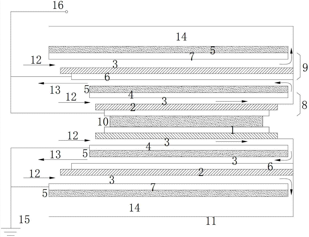
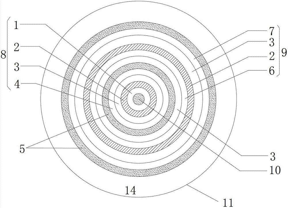
[0033] figure 1 It is a cross-sectional view of the multiple ozone generating equipment. figure 2 It is a side view of multiple ozone generating equipment. Such as Figure 1-2 As shown, the multiple ozone generating equipment is composed of multiple electrode pairs distributed in concentric circles from the inside to the outside.

[0034] Each of the electrodes includes an inner electrode and an outer electrode, the inner electrode is connected to a high-voltage terminal 16, the outer electrode is grounded 15, and a discharge gap 3 is formed between the inner electrode and the outer electrode. A discharge gap 3 is formed between the electrode pairs.

[0035] The cooling liquid is arranged on the outer side of the outer electrodes of the pair of electrodes and the innermost layer of the concentric circles.

[0036] The jacket is arranged on the outermost layer of the plurality of electrodes, and a stainless steel jacket 11 can be used.

[0037] Such as Figure 1-2 As sho...

Embodiment 2

[0051] Use the iodometric method specified in the CJ / T322-2010 "Ozone Generator for Water Treatment" standard to detect the concentration and output of ozone. Using this equipment, compared with the general corona discharge type ozone generating equipment, the ozone gas production rate should be increased by at least 30-40%, the ozone concentration can reach 60-170mg / L, and the power consumption per kilogram of ozone can be reduced to 15KWh. Power consumption per kilogram of ozone is reduced by 20-30%, and if the production of 20Kg / h equipment can reduce the area of ​​equipment by 40m 2 About 20-40% reduction in floor space.


PUM


Abstract

The invention discloses a multiple ozone generating device which is formed by a plurality of electrode couples, and the electrode couples are distributed from inside to outside in a concentric-circle mode in sequence. Each electrode couple is composed of an inner electrode and an outer electrode, the inner electrode is connected with a high-voltage terminal, the outer electrode is grounded, the inner electrode of each electrode couple is coated with dielectrics, a discharging gap is arranged between the inner electrode and the outer electrode, and a discharging gap is arranged between two adjacent electrode couples. Double cooling liquid is used in the multiple ozone generating device, a cooling oil layer is arranged on the outer side of each outer electrode, and the innermost layer of the device is filled with cooling water. The discharging gap of each electrode couple and the discharging gap between the electrode couple and the adjacent electrode couple on the outer layer are in a communicating state, and a stainless steel jacket is arranged on the outermost layer of the whole device. The technical problems that the efficiency of existing high-voltage corona discharge type ozone generating is low, an ozone generating device is high in running cost and the like are solved, the use ratio of raw material gas is improved, ozone concentration is increased, and discharging tube consumption and electric-discharge energy consumption are reduced, so that cost is lowered.

Description

technical field [0001] The invention belongs to the fields of energy saving and environmental protection, electronics and electrochemistry, and in particular relates to a multiple ozone generating device. Background technique [0002] Ozone has one more active oxygen atom than oxygen molecules. Ozone is very active in chemical properties. It is a strong oxidant that can quickly kill bacteria in the air at a certain concentration without any toxic residue and will not form secondary pollution. Known as "the cleanest oxidizer and disinfectant". However, ozone is easy to decompose and cannot be stored, so it needs to be produced on-site and used on-site. Any place where ozone can be used needs to use an ozone generator. [0003] Ozone generators are equipment used to produce ozone. Ozone generators are widely used in tap water, sewage, industrial oxidation, space sterilization and other fields, and have achieved good results. The ozone generator uses air or oxygen as the raw ...

Claims


Application Information

Patent Timeline
IPC IPC(8): C01B13/11
Inventor 伊学农宋桃莉金鑫王峰赵青
Owner UNIV OF SHANGHAI FOR SCI & TECH
Learn More