
Vehicle comprising a traction battery which can absorb crash energy

A technology of vehicles and batteries, applied in the field of vehicles

Active Publication Date: 2013-06-12
AUDI AG
View PDF7 Cites 12 Cited by
  • Summary
  • Abstract
  • Description
  • Claims
  • Application Information

AI Technical Summary

Problems solved by technology

But this requires a lot of material to be used in the design of the housing parts

Method used


Image

  • Vehicle comprising a traction battery which can absorb crash energy
  • Vehicle comprising a traction battery which can absorb crash energy

Examples


Embodiment Construction

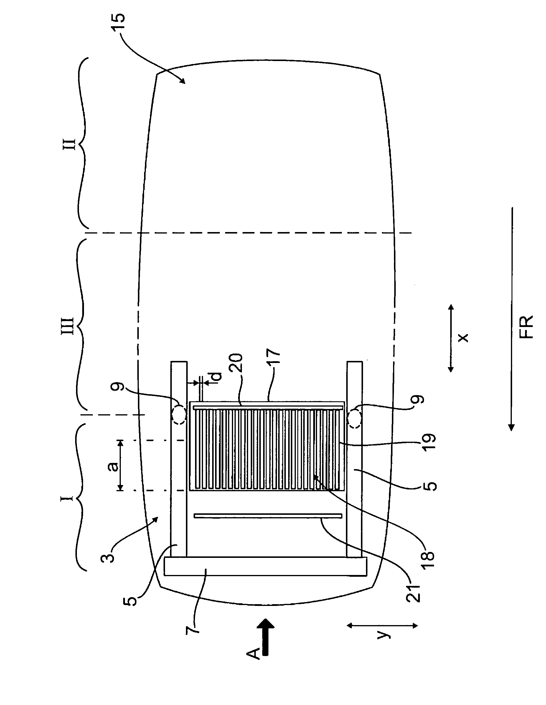
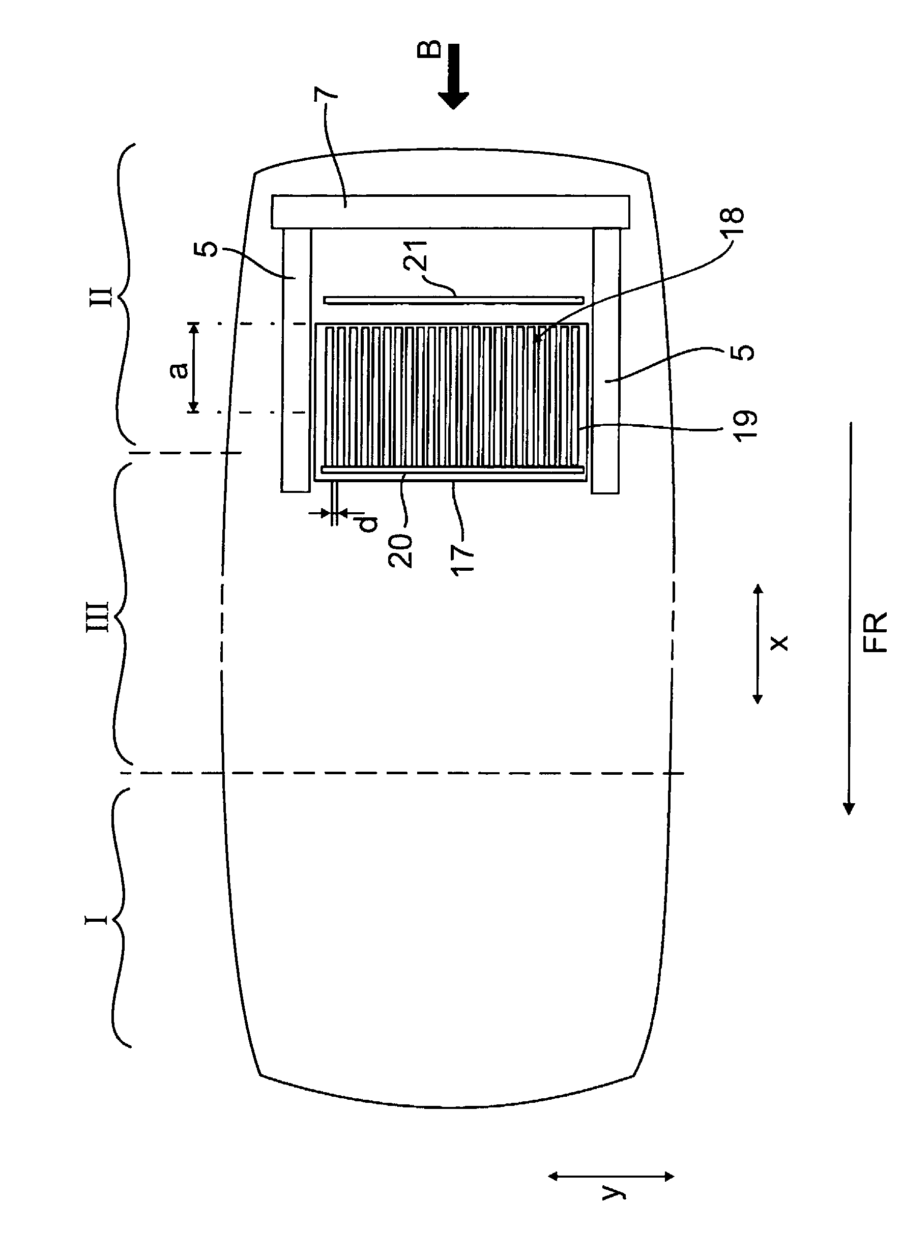
[0020] figure 1 A vehicle is shown schematically, the drive system of which has at least one electric machine (not shown), which is supplied with electrical energy via a rechargeable driving battery 1 . exist figure 1 In this case, the drive battery 1 is arranged in the front vehicle area 3 of the motor vehicle. Such as figure 1 As also shown in FIG. 2 , two lateral body side members 5 extend in the front vehicle area 3 , which are closed at the vehicle front side in a transversely extending bumper 7 . A lateral spring strut assembly receptacle 9 of the wheel suspension of the front wheel 13 is formed on the two side members 5 in the front vehicle area 3 .

[0021] according to figure 1 The vehicle is divided into different zones, namely deformation zone I in the front vehicle area 3 and deformation zone II in the rear vehicle area 15 and a high component stiffness zone between the two deformation zones I, II, the passenger compartment lies in this region of high componen...


PUM


Abstract

The invention relates to a vehicle comprising an at least partial electric drive which comprises a traction battery (1), which vehicle has at least one predefined deformation zone (I, II) which in the event of a crash (A, B) acts to absorb energy, and at least one predefined zone (III), which has high component rigidity and which in the event of a crash (A, B) remains substantially without deformation. According to the invention, the traction battery (1) has a deformation region (18) which in the event of a crash can be deformed via a deformation path (a) and which is arranged in the deformation zone (I, II) of the vehicle.

Description

technical field [0001] The invention relates to a vehicle according to the preamble of claim 1 , the drive system of which is at least partially electric. Background technique [0002] Use traction batteries in hybrid vehicles or in pure electric vehicles. The traction battery is arranged as a structurally space-intensive component in the front or rear vehicle area and is therefore subject to a high risk of deformation in the event of a crash. [0003] To avoid damage to the traction battery due to accidents, DE 10 2008 010 829 A1 discloses a vehicle of this type with such a traction battery. The battery housing of the traction battery is divided into two battery housing parts which can be connected to one another. The two battery housing parts are aligned with each other in such a way that the battery as a whole is protected from damage in the event of a crash. [0004] In order to ensure the protection of the occupants in the event of a crash on the one hand and to ensu...

Claims


Application Information

Patent Timeline
Patent Type & Authority Applications(China)
IPC IPC(8): H01M2/10H01M2/20B60K1/04B62D21/15B62D25/20H01M50/227H01M50/249H01M50/502
CPCB60K1/04B60K2001/0411B60K2001/0416B62D21/15B62D21/152B60L50/64Y02T10/70Y02E60/10H01M50/24H01M50/502Y02P70/50H01M10/04H01M50/227H01M50/249
Inventor N·恩宁
Owner AUDI AG
Learn More