
Light-emitting diode (LED) electrolytic capacitor-free constant current power supply

A technology of constant current power supply and electrolytic capacitor, applied in electrical components, conversion equipment without intermediate conversion to AC, conversion of AC power input to DC power output, etc. To solve the problems such as transformation, to achieve the effect of simple structure, small size, and easy integration

Active Publication Date: 2013-06-12
湖北湛青科技股份有限公司
View PDF6 Cites 1 Cited by
  • Summary
  • Abstract
  • Description
  • Claims
  • Application Information

AI Technical Summary

Problems solved by technology

[0002] LED lighting has been widely used. Practice has proved that constant LED power supply current can effectively improve the service life of light-emitting light sources, that is, light-emitting diodes. Theoretically, the service life of LEDs can reach 50,000 hours, but the service life of the matching power supply is difficult to reach this life. , which affects the service life of the entire LED. The main component that restricts the service life of the power supply is the electrolytic capacitor, and the temperature has a significant impact on the electrolytic capacitor. Compared with other components, the electrolytic capacitor is relatively large in size and is not convenient for miniaturization.

Method used


Image

  • Light-emitting diode (LED) electrolytic capacitor-free constant current power supply

Examples


Embodiment Construction

[0019] Specific embodiments of the present invention will be described in detail below in conjunction with the accompanying drawings.

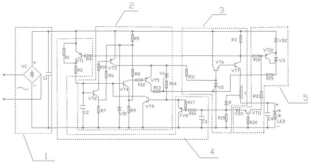
[0020] An LED non-electrolytic capacitor constant current power supply, comprising a rectification circuit 1, a frequency conversion circuit 2, a push output circuit 3, a feedback control circuit 4, and a feedback protection circuit 5, characterized in that:

[0021] The rectifier circuit 1 includes a full bridge block VC and a capacitor C1, the two ends of the capacitor C1 are directly connected to the output positive and negative terminals of the full bridge block, and the positive and negative terminals are used as the positive and negative terminals of the whole circuit;

[0022] The frequency conversion circuit 2 is connected by the two ends of the resistor R1 and the emitter and collector of the triode VT1, the emitter of VT1 is connected to the positive terminal, the collector is connected to the negative terminal in series with the resi...


PUM


Abstract

The invention discloses a light-emitting diode (LED) electrolytic capacitor-free constant current power supply, which comprises a rectifying circuit, a frequency conversion circuit, a driving output circuit, a feedback control circuit and a feedback protection circuit. Constant current feedback information is controlled to be fed back by three paths. The first path refers to that external voltage is fed back through a resistor R1 and a triode VT1; the second path refers to that current flowing through an auto-transformer is fed back through a resistor R3 when frequency is low; and the third path refers to that transformation current of the auto-transformer is fed back through a resistor R15 when the frequency is high. According to the LED electrolytic capacitor-free constant current power supply disclosed by the invention, the output current is average current which consists of direct-current pulses. According to external voltage changes, output pulse widths also are different. The constant current refers to the average current of the LED electrolytic capacitor-free constant current power supply in a certain period. The LED electrolytic capacitor-free constant current power supply disclosed by the invention is simple in structure. The requirement of a traditional constant current power supply on an electrolytic capacitor is met. The electrolytic capacitor is removed, so that the constant current power supply can be made to be smaller in size; the circuits can be conveniently integrated. The LED electrolytic capacitor-free constant current power supply can work under an environment with higher temperature, and the service life of the LED electrolytic capacitor-free constant current power supply is longer than that of the constant current power supply with the electrolytic capacitor.

Description

technical field [0001] The invention relates to the field of power circuits, in particular to a constant-current power supply for LEDs without electrolytic capacitors. The utility model has the advantages of simple structure, convenient miniaturization and integration, no electrolytic capacitor, certain high temperature resistance, long service life and energy saving. Background technique [0002] LED lighting has been widely used. Practice has proved that constant LED power supply current can effectively improve the service life of light-emitting light sources, that is, light-emitting diodes. Theoretically, the service life of LEDs can reach 50,000 hours, but the service life of the matching power supply is difficult to reach this life. , which affects the service life of the entire LED. The main component that restricts the service life of the power supply is the electrolytic capacitor, and the temperature has a significant impact on the electrolytic capacitor. Compared wi...

Claims


Application Information

Patent Timeline
Patent Type & Authority Applications(China)
IPC IPC(8): H02M7/155H02M3/07H02M1/32
Inventor 余碧峰
Owner 湖北湛青科技股份有限公司
Learn More