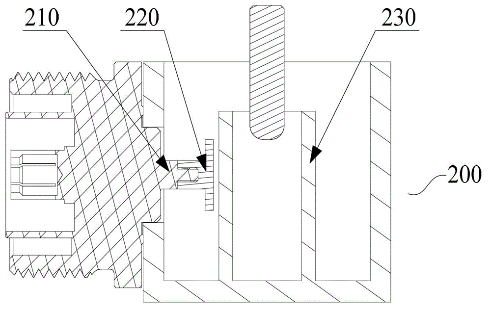
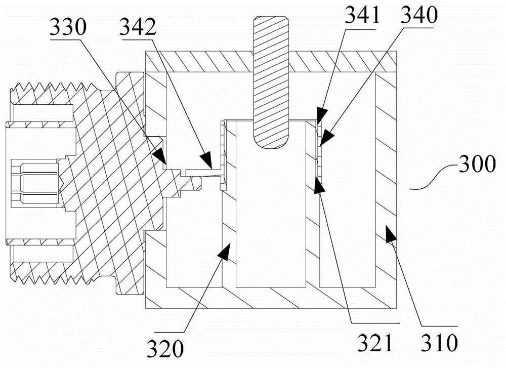
Cavity filter, radio-frequency zooming-out equipment, signal receiving-transmitting device and tower top amplifier
A cavity filter and low-noise amplifier technology, applied in the field of communication radio frequency, can solve the problems of limited coupling area of the coupling disc, large filter area, changes in radio frequency parameters, etc., achieve good consistency, optimize cavity space, position and Dimensionally stable effect
- Summary
- Abstract
- Description
- Claims
- Application Information
AI Technical Summary
Problems solved by technology
Method used
Image
Examples
Embodiment 1
[0036] The coupling body is sleeved on the outer surface of the resonant rod, and the coupling body is an annular body. The shape of the coupling body can be changed into different shapes according to the shape of the resonant rod, and the cross section can be circular, square, hexagonal, etc., which does not constitute a limitation to the present invention. Such as Figure 4 As shown, the coupling body can be a closed ring body 400, which can be processed by die-casting or machining. Such as Figure 5 As shown, the coupling body can also be a ring body 500 with a notch 501 on the side wall, and the ring body with the notch can be realized by stamping, and the cost is relatively low. In addition, if the coupling body has a notch, the elasticity of the ring body with the notch can be used to directly sleeve the coupling body at a suitable position on the outer surface of the resonant rod. The ring-shaped coupling body can also be fixed on the resonant rod by other technical ...
Embodiment 2
[0039] In this embodiment, the coupling body is a patch attached to the outer surface of the resonating rod, and the patch can be glued or fixed on the outer surface of the resonating rod in other forms. The shape of the patch can be rectangular, square, circular, etc., and the area of the patch can be determined according to the required coupling amount. The shape and area of the patch do not limit the present invention. The coupling body in the form of a patch is easy to process, low in cost, and easy to fix. The connector can be integrally formed with the patch, or welded on the patch.
Embodiment 3
[0041] In this embodiment, the coupling body is a metal layer covering the insulating dielectric layer. The metal layer can be implemented by spraying or electroplating. First, an insulating dielectric layer is coated on a suitable position on the outer surface of the resonating rod, and then a metal layer is coated on the outer surface of the insulating dielectric layer. Connectors for transmitting signals can be soldered to the metal layer. This method can make the structure inside the cavity filter cavity smoother, and the radio frequency index is better.
[0042] The embodiment of the present invention also provides a radio remote device, including: including a radio frequency transceiver module, a power amplifier module and the cavity filter described in all the above embodiments, the radio frequency transceiver module and the power amplifier The modules are connected, and the power amplifier module is connected with the filter. When the RRU works in the downlink time s...
PUM
 Abstract
Description
Claims
Application Information
 - R&D Engineer
- R&D Manager
- IP Professional
- Industry Leading Data Capabilities
- Powerful AI technology
- Patent DNA Extraction
Browse by: Latest US Patents, China's latest patents, Technical Efficacy Thesaurus, Application Domain, Technology Topic, Popular Technical Reports.
© 2024 PatSnap. All rights reserved.Legal|Privacy policy|Modern Slavery Act Transparency Statement|Sitemap|About US| Contact US: help@patsnap.com


