
Cutting device

A technology of cutting device and placing groove, applied in sampling device and other directions, can solve the problems of easily changing the shape and position of sediment, slow manual cutting speed, affecting the efficiency of research progress, etc., to achieve no debris pollution, ensure safety, and ensure cutting accuracy. high effect

Active Publication Date: 2015-03-18
INST OF GEOLOGY & GEOPHYSICS CHINESE ACAD OF SCI
View PDF4 Cites 0 Cited by
  • Summary
  • Abstract
  • Description
  • Claims
  • Application Information

AI Technical Summary

Problems solved by technology

Since the deposits are generally soft, the shape and position of the deposits are easily changed due to the pressure and the drive of the tool during cutting, so as to confuse samples of different depths and affect the results of test research. In addition, the manual cutting speed is slow, which affects the efficiency of research progress.

Method used


Image

  • Cutting device

Examples


Embodiment Construction

[0016] Specific embodiments of the present invention will be described in detail below with reference to the accompanying drawings.

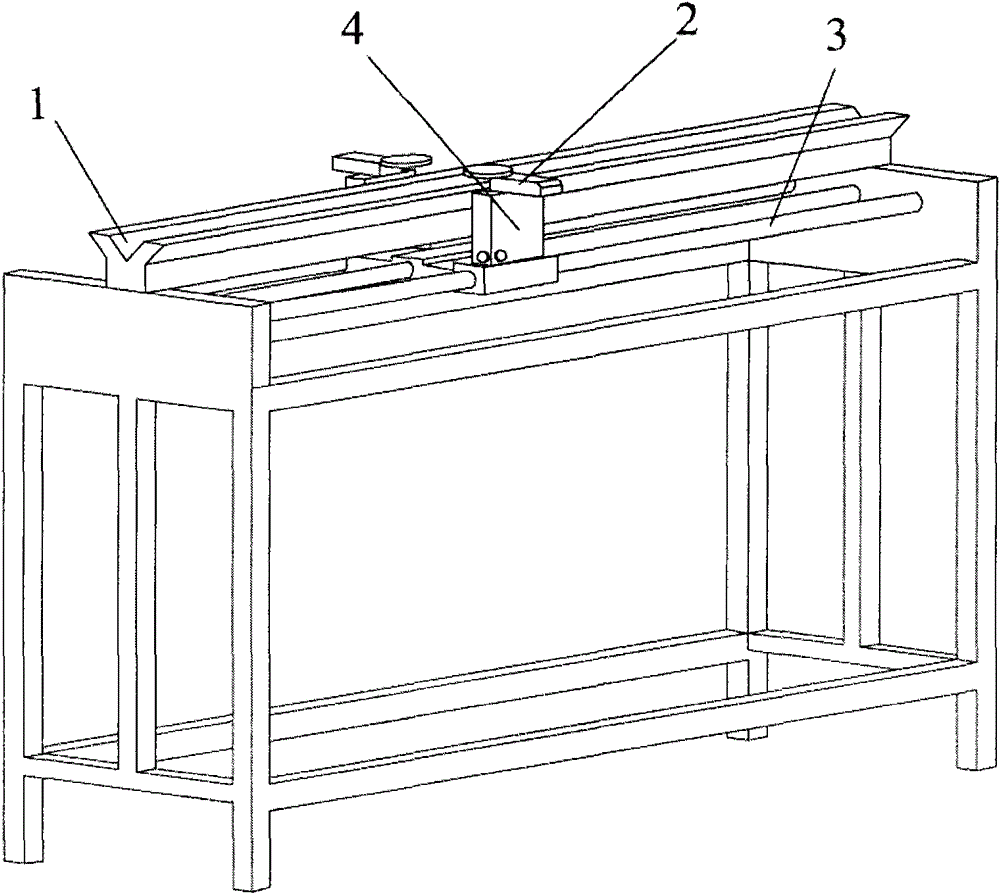
[0017] see figure 1 Describe the cutting device of the present invention, which includes: a bracket provided with a sample placement groove 1; a lead screw 3 that is rotatably supported on the bracket and parallel to the placement groove 1, and the lead screw is driven to rotate by a stepping motor; installed on the lead screw 3 The workbench 4 on the top, wherein a spiral connection is formed between the workbench 4 and the lead screw 3, so that the workbench 4 slides reciprocally along the lead screw 3; the vibration cutting probe 2 installed on the workbench 4 for cutting samples; the control terminal , which is electrically connected with the vibrating cutting probe and the motor driving the lead screw, where the cutting position (that is, the cutting displacement of the cutting probe, including the cutting start point, cutting end point, an...


PUM


Abstract

The invention provides a cutting device comprising a support, a screw rod (3), a work table (4), a vibration cutting probe (2) and a control terminal. The support is provided with a sample placement groove (1). The screw rod (3) is controlled by a step motor to be rotatably supported on the support and is parallel with the sample placement groove (1). The work table (4) is connected with the screw rod (3) in a screwed mode and slides along the screw rod (3) in a reciprocated mode. The vibration cutting probe (2), vertical to the direction of the sample placement groove (1), is installed on the work table (4) in a sliding mode. By means of the control terminal, cutting displacement, a moving speed, vibration frequency of the cutting probe (2) can be set, and the control terminal is in electric connection with the step motor and the vibration cutting probe (2). The cutting device improves a cutting speed, prevents shapes of cut samples from being influenced, and does not cause secondary pollution.

Description

technical field [0001] The invention relates to a cutting device. Background technique [0002] Ocean and lake sediments are important research objects in oceanography, paleoclimate-environmental science, paleogeography, paleontology, paleomagnetism and other scientific research. Generally, gravity drills and hollow electric drills are used for sediment core sampling, and the in-situ sediment samples are pressed into plastic pipes such as PVC, and taken to the laboratory for cutting and separation, and then the samples are extracted for specific testing and research, because different depths The samples contain features corresponding to different geological ages. When separating samples, it is necessary to record the depth of the samples. Samples of different depths cannot be confused, and it is necessary to ensure that the shape of the samples is not affected. At present, it is necessary to manually cut the plastic tube containing the sample with a knife, and then divide t...

Claims


Application Information

Patent Timeline
Patent Type & Authority Patents(China)
IPC IPC(8): G01N1/04
Inventor 刘双迟刘青松秦华峰赵翔朱日祥
Owner INST OF GEOLOGY & GEOPHYSICS CHINESE ACAD OF SCI
Learn More