
Plastic enclosed impeller manufacturing technique

A closed impeller and production process technology, which is applied in the production process field of plastic closed impellers, can solve the problems of destroying the hydraulic performance of the blade, reducing the efficiency of the impeller, and not being able to suppress the impeller, so as to achieve safe and reliable performance, improve hydraulic performance, Guarantee the effect of performance

Inactive Publication Date: 2013-06-05
黄晓鹏 +1
View PDF2 Cites 9 Cited by
  • Summary
  • Abstract
  • Description
  • Claims
  • Application Information

AI Technical Summary

Problems solved by technology

For easy demolding, the impeller blades are often single-curvature and rounded into several arcs. Although this is easy to demould, it destroys the hydraulic performance of the blades and reduces the efficiency of the impeller; at the same time, one impeller mold corresponds to a set of Design parameters, in this way, the use function of the mold cannot be fully utilized, and it cannot meet various working conditions, and the investment of the mold is relatively large, the cost is high, and the mold structure is complicated
Although the double-curvature blade has high efficiency, because it is a closed impeller, the plug of the impeller mold cannot be removed, and the impeller cannot be pressed
Therefore, none of the existing production processes can provide an economical, efficient, simple-structured, variable-parameter closed impeller of a plastic-lined pump.

Method used


Image

  • Plastic enclosed impeller manufacturing technique
  • Plastic enclosed impeller manufacturing technique
  • Plastic enclosed impeller manufacturing technique

Examples


Embodiment Construction

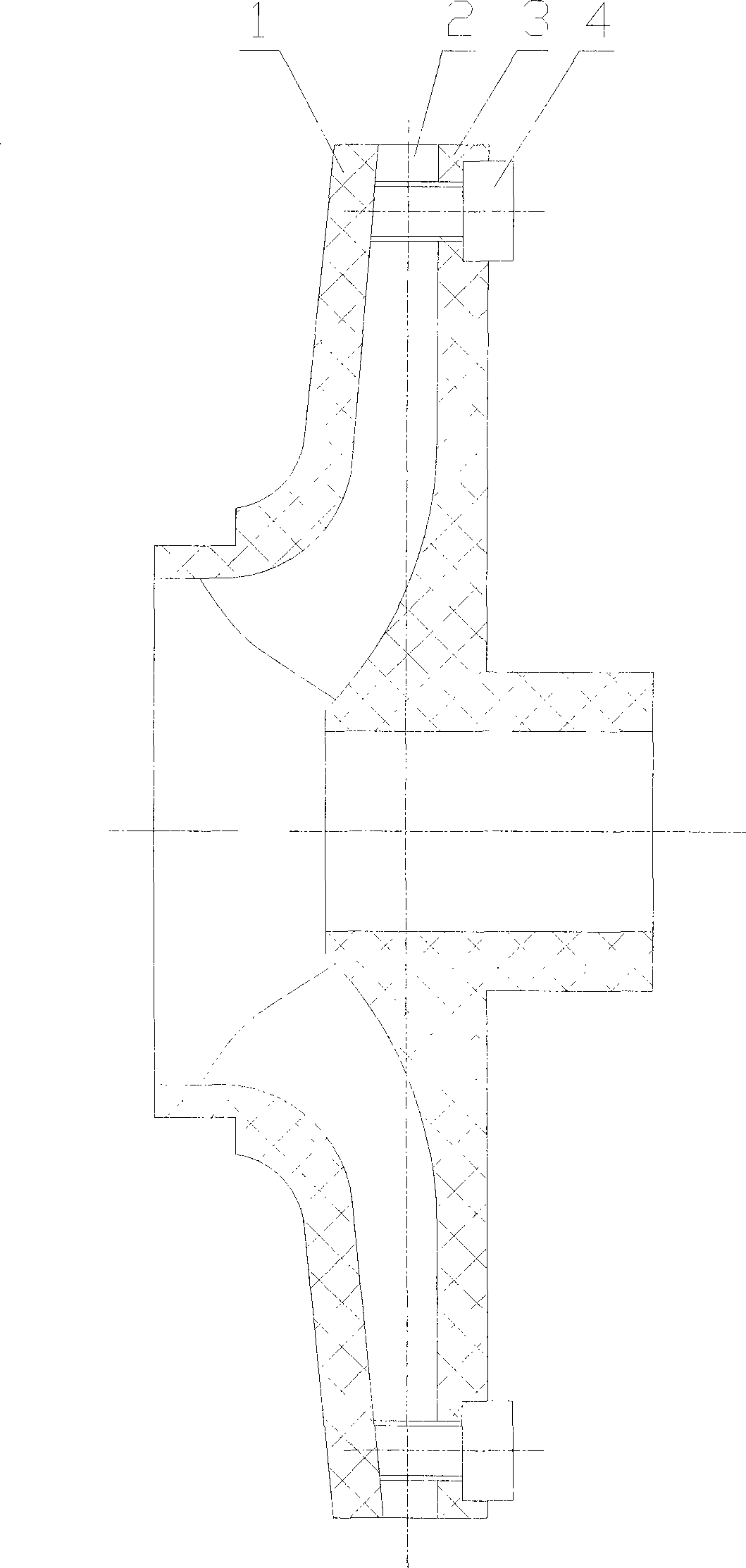
[0023] A production process of a plastic closed impeller of a plastic lining pump is characterized in that its process steps are as follows:

[0024] 1. Design as Figure 4 For the impeller front cover mold shown above, evenly coat 0.1mm of release agent on the inner surface of the impeller front cover mold, heat to 100°C in a heating box, and keep it warm for 30 minutes;

[0025] 2. Add 720 grams of FEP pellets into the heated mold, cover the upper mold (10) tightly, put it into the heating box and heat it to 320°C ± 2°C, and keep it warm for 3 hours;

[0026] 3. Put the well-insulated mold quickly on the press and slowly pressurize to 10Mpa, keep the pressure for 2 hours, cool naturally in the air, demould and take out the front cover (1);

[0027] 4. Design as Figure 5 For the impeller rear cover mold shown, evenly coat the inner surface of the impeller rear cover mold with 0.1mm release agent, heat it to 100°C in the heating box, and keep it warm for 30 minutes;

[002...


PUM


Abstract

The invention relates to a plastic enclosed impeller manufacturing technique of a plastic lining pump. The plastic enclosed impeller manufacturing technique is characterized by comprising the following processing steps: adding 720 grams of tetrafluoroethylene-hexafluoropropylene copolymer granules into the mold of a front shroud, heating the tetrafluoroethylene-hexafluoropropylene copolymer granules to 320 DEG C + / - 2DEG C in a heating box, carrying out heat preservation for 3 hours, then pressurizing 10 MPa in a pressing machine, maintaining pressure for 2 hours, carrying out natural cooling in air, and demoulding to take out a front shroud; adding 512 grams of tetrafluoroethylene-hexafluoropropylene copolymer granules into the mold of a back shroud, heating the tetrafluoroethylene-hexafluoropropylene copolymer granules to 320 DEG C + / - 2DEG C in the heating box, carrying out heat preservation for 2 hours, then pressurizing 10 MPa in the pressing machine, maintaining pressure for 1.5 hours, carrying out natural cooling in air, and demoulding to take out a back shroud; and using teflon bar materials to process screws to connect the front shroud and the back shroud. The manufacturing technique guarantees the separated pressing of the front shroud and the back shroud through a pressing technique, a blade can be made into a double curvature shape, and therefore the hydraulic performance of an impeller is improved, and a manufacturing technology is simple, production cost is low, and the plastic enclosed impeller manufacturing technique can meet the usability of the plastic enclosed impeller completely.

Description

technical field [0001] The invention relates to a production process of a plastic closed impeller of a plastic lining pump. Background technique [0002] The impeller is the most important working element of the pump, the core of the flow-passing parts, and the most important element affecting the efficiency of the pump, so the design of the impeller is the key to the pump design. The impeller is divided into closed type, semi-open type and open type impeller according to the geometric shape. At present, the plastic-lined pump mainly adopts a closed impeller, and the blade form is a single-curvature blade, which is mainly limited by the pressing process of the plastic impeller. For easy demolding, the impeller blades are often single-curvature and rounded into several arcs. Although this is easy to demould, it destroys the hydraulic performance of the blades and reduces the efficiency of the impeller; at the same time, one impeller mold corresponds to a set of Design param...

Claims


Application Information

Patent Timeline
IPC IPC(8): B29C69/00B29C43/00B29C65/56B29L31/08
Inventor 黄晓鹏万芳新
Owner 黄晓鹏
Learn More