
Thin metal belt ring rolling mill

A thin metal and ring technology, applied in metal rolling and other directions, can solve the problems of low rolling efficiency, metal ring offset, poor stability, etc., to improve product forming accuracy and rolling efficiency, and ensure consistency and stability. Precision control, the effect of reducing human factors

Inactive Publication Date: 2015-01-07
CHONGQING UNIV OF TECH
View PDF6 Cites 0 Cited by
  • Summary
  • Abstract
  • Description
  • Claims
  • Application Information

AI Technical Summary

Problems solved by technology

From the partially disclosed thin strip ring manufacturing technology, there are mainly problems in the following aspects: 1. The rolled metal thin strip ring has low precision and poor stability
2. Low rolling efficiency and many human factors
3. Due to the inertia of the rolling roll, it cannot be stopped immediately after the end command is issued, and the metal thin strip ring will be subjected to additional rolling
4. The position deviation of the metal belt ring on the roll during the rolling process

Method used


Image

  • Thin metal belt ring rolling mill

Examples


Embodiment Construction

[0019] The present invention will be further described below with reference to the accompanying drawings and specific embodiments.

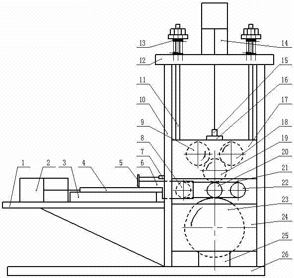
[0020] like figure 1 As shown, the metal thin strip ring rolling mill of the present invention includes a base 26 on which a bracket composed of four uprights 10 and beams 12 is arranged. A lower support seat 24 and an upper support seat 17 are arranged in the bracket, the lower support seat is located under the upper support seat, the lower support seat 24 is provided with a lower rolling roller 23, and the lower rolling roller is connected with the main motor and is driven by the main motor. Roller turns. Guide chutes are provided inside the four uprights 10, and the upper support base 17 can slide up and down along the uprights guide chute. The upper support base 17 is provided with a left pressure roller 9, a right pressure roller 18 and an upper floating pressure roller 19 of the same size. The left pressure roller 9 and the right pressure...


PUM


Abstract

The invention discloses a metal belt ring rolling mill which is characterized in that a support is arranged on the base, an upper supporting seat and a lower supporting seat are arranged in the support, a lower rolling roller is arranged in the lower supporting seat, and the upper supporting seat can slide along the support up and down under the action of a hydraulic mechanism. A left compression roller, a right compression roller and an upper floating compression roller are arranged in the upper supporting seat; a draw roller, a fixing roller and a middle rolling roller of the same heights are arranged between the lower supporting seat and the upper supporting seat; the draw roller and the fixing roller can be used for being sleeved in a thin metal belt ring to tension the thin metal belt ring; a stretching mechanism which drives the draw roller to move left and right is arranged in the base. According to the metal belt ring rolling mill, a rolling force is controllable in a rolling process, and therefore control of uniformity and precision of metal ring finished thicknesses can be effectively guaranteed. The circumference precision of a metal ring is guaranteed by the fact that a displacement sensor detects the length of the metal ring in an on-line mode. Meanwhile, the problem of 'off tracking' of the metal ring in the rolling process can be solved.

Description

technical field [0001] The invention relates to the improvement of metal thin strip ring rolling technology, in particular to a metal thin strip ring rolling mill used for a metal strip assembly of a continuously variable transmission device, and belongs to the technical field of metal thin strip ring rolling. Background technique [0002] Continuously variable transmission is one of the advanced transmission methods of automobiles. Among them, the metal belt type continuously variable transmission is the main one, and the metal belt, one of its main core components, is composed of two sets of multi-layer thin belt rings and hundreds of thrust plates. For the above-mentioned thin strip ring, firstly, a section of steel strip made of high-strength alloy steel is welded into a ring at both ends, and then it is cut into narrow metal rings of equal width, and finally the metal ring is made into a certain length by rolling method. thin belt loop. [0003] At present, only t...

Claims


Application Information

Patent Timeline
Patent Type & Authority Patents(China)
IPC IPC(8): B21B5/00
Inventor 蒋强
Owner CHONGQING UNIV OF TECH
Learn More