
Illumination device having a heat sink and method for directing a light bundle emitted by an illumination device

A lighting device and cooling body technology, which is applied to the cooling/heating device of the lighting device, the parts of the lighting device, the lighting device, etc., can solve the problem of ineffective heat conduction, and achieve the reduction of transfer thermal resistance, easy realization and improvement cooling effect

Inactive Publication Date: 2013-05-22
OSRAM GMBH
View PDF3 Cites 3 Cited by
  • Summary
  • Abstract
  • Description
  • Claims
  • Application Information

AI Technical Summary

Problems solved by technology

[0003] In general, the known lighting devices have the disadvantage that the conduction of heat through the joint is not very efficient and that the cooling of the luminous means takes place only by means of a cooling body present between the joint and the illuminant, which is particularly the case with compact and intensely luminous is problematic in illuminants of

Method used


Image

  • Illumination device having a heat sink and method for directing a light bundle emitted by an illumination device
  • Illumination device having a heat sink and method for directing a light bundle emitted by an illumination device
  • Illumination device having a heat sink and method for directing a light bundle emitted by an illumination device

Examples


Embodiment Construction

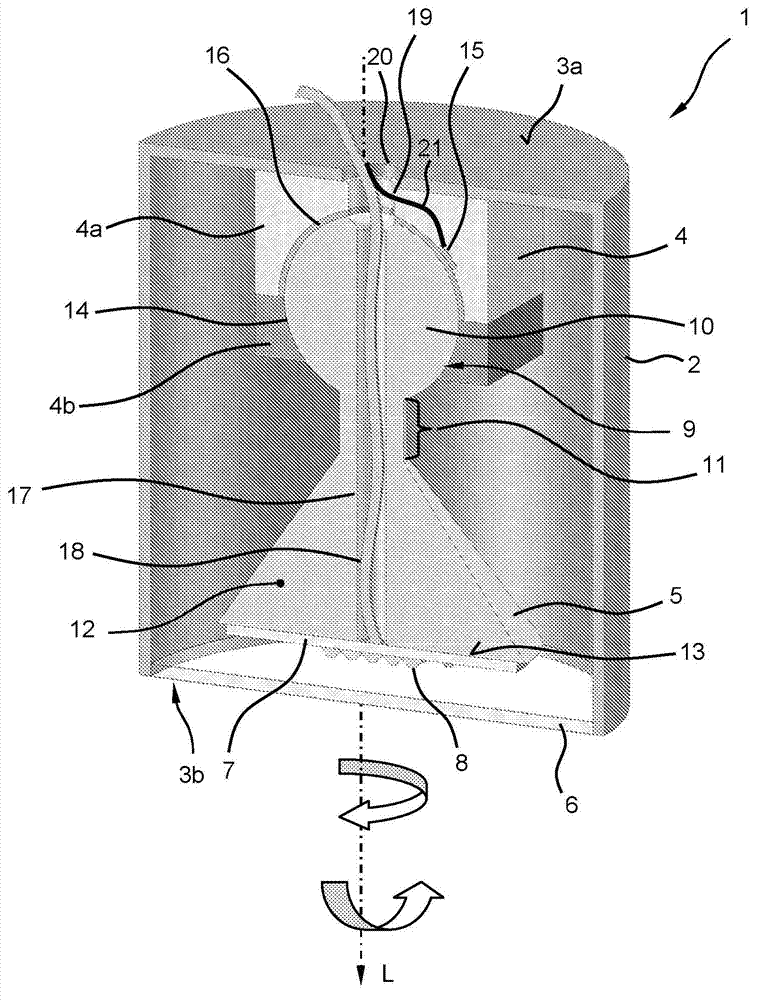
[0041] figure 1 An oblique sectional view of the lighting device 1 according to the first embodiment is shown. The lighting device 1 has a hollow-cylindrical housing 2 , on a closed cover surface 3 a of which a support 4 is fastened inside. The carrier 4 holds or carries a cooling body 5 , wherein the cooling body 5 extends from the carrier 4 in the direction of the open cover surface 3 b of the housing 2 opposite the closed cover surface 3 a . The open cover surface 3 b is covered by means of a disc-shaped and light-permeable cover 6 .

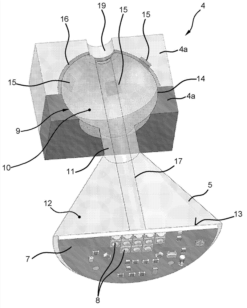
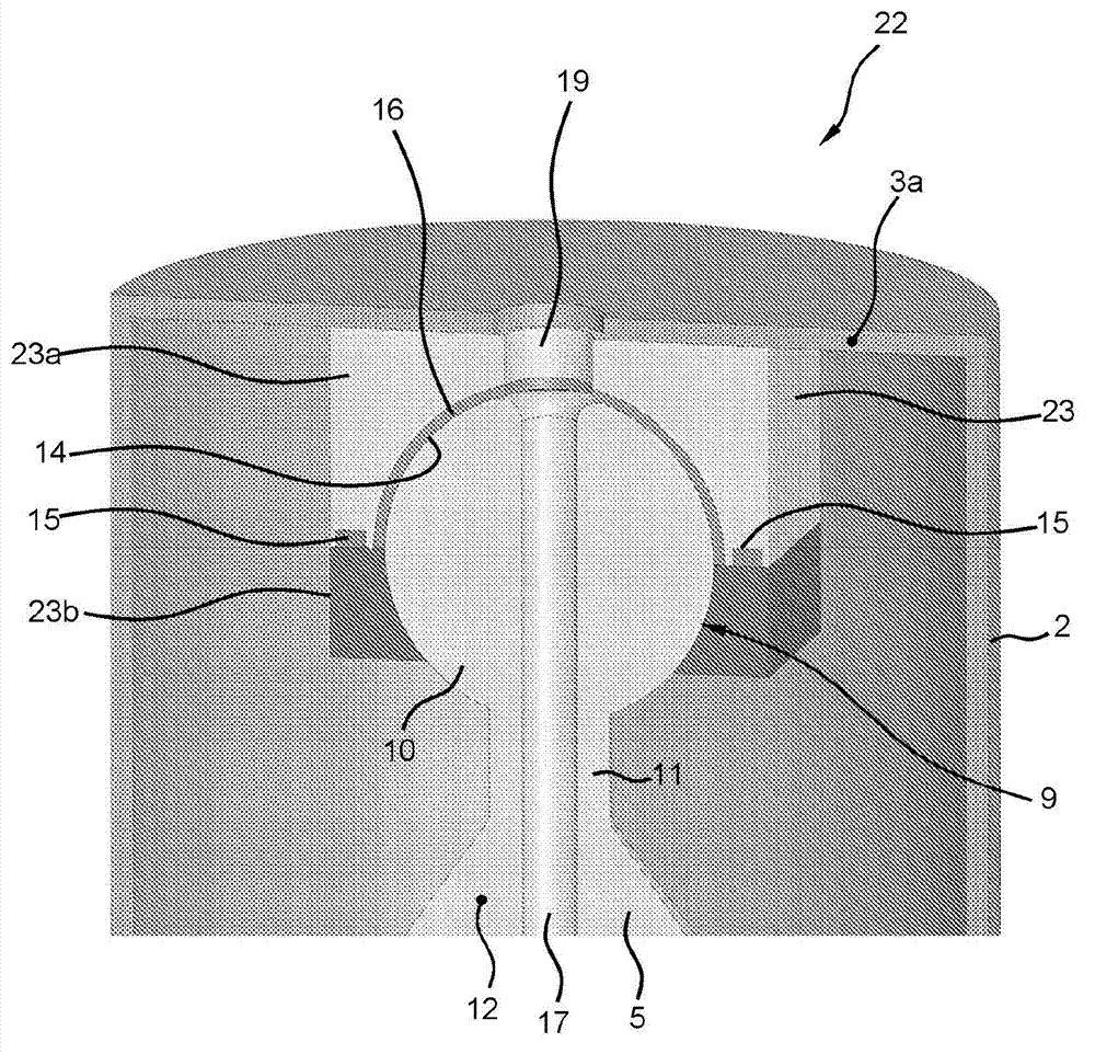
[0042] The carrier 4 forms a spherically-truncated recess in the form of a socket 9 for accommodating a spherical-head-shaped fastening region 10 of the heat sink 5 . The spherical fastening region 10 is the rear end of the heat sink 5 . In order to introduce a ball-shaped fastening area into the joint socket 9, the bracket 4 is designed in two parts, that is to say, with a first bracket part 4a fastened to the cover surface 3a and a The ...


PUM


Abstract

An illumination device may include a heat sink, on which at least one light source is fastened at least indirectly, wherein the heat sink is held movably in a holder in such a way that the heat sink moves with greater difficulty in an energized state of the light source than in a de-energized state of the light source.

Description

technical field [0001] The invention relates to a lighting device, in particular a semiconductor lighting device, with a heat sink. Furthermore, the invention relates to a method for directing a light beam emitted by a lighting device, in particular a semiconductor lighting device. Background technique [0002] Lights are known which have a base for the luminous means, wherein the base can be manually aligned by means of a mechanical joint. The mobility of the joint is fixedly preset by manufacture or can be manually adjusted by the user. [0003] In general, the known lighting devices have the disadvantage that the heat conduction via the joint is not very effective and that the cooling of the luminous means takes place only by means of a cooling body present between the joint and the illuminant, which is particularly the case with compact and intensely luminous is problematic in illuminants. Contents of the invention [0004] It is an object of the invention to at lea...

Claims


Application Information

Patent Timeline
IPC IPC(8): F21V21/096F21V21/29F21V29/00F21V21/15F21Y101/02
CPCF21V21/096F21V21/29F21V29/22F21V21/15F21Y2101/02F21V29/004F21V29/70F21Y2115/10
Inventor 彼得·萨克森韦格
Owner OSRAM GMBH
Learn More