Unmanned aerial vehicle obstacle avoidance controlling method
A control method and unmanned aerial vehicle technology, applied in the direction of three-dimensional position/channel control, etc., to reduce the probability of collision with obstacles, improve safety, and be easy to implement
- Summary
- Abstract
- Description
- Claims
- Application Information
AI Technical Summary
Problems solved by technology
Method used
Image
Examples
Embodiment 1
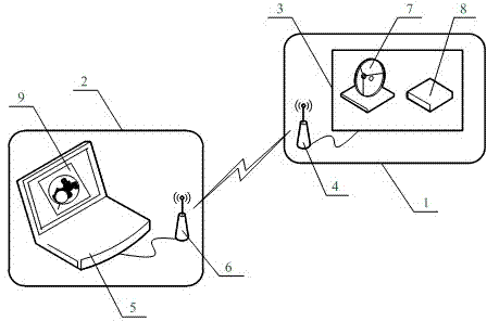
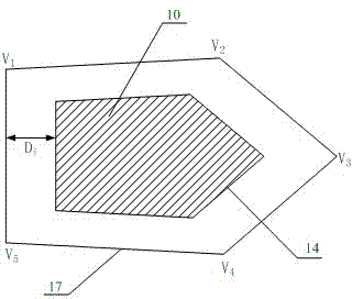
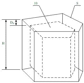
[0042] Embodiment 1: as figure 1 , UAV obstacle avoidance control system based on columnar space planning constraints, with UAV subsystem 1 and ground station subsystem 2; UAV subsystem 1 includes embedded flight controller 3 and airborne terminal 4 of wireless data link , the embedded flight controller 3 has a built-in satellite positioning receiver 7 and a height sensor 8; the ground station subsystem 2 includes an embedded monitoring computer 5 and a ground terminal 6 of a wireless data link, and the embedded monitoring computer 5 has a built-in monitoring system that contains geographic information of obstacles electronically Figure 9 The embedded flight controller 3 is connected with the airborne terminal 4 of the wireless data link by a serial bus, the embedded monitoring computer 5 is connected with the ground terminal 6 of the wireless data link by a serial bus, and the airborne terminal 4 of the wireless data link is connected with the wireless data link The ground ...
Embodiment 2
[0051] Embodiment 2: as Figure 4 As shown, for an obstacle with an arc-shaped boundary, the two-dimensional geographical boundary of the obstacle is surrounded by N straight line segments to form a closed boundary contour line 14, the method is as follows:
[0052] ① The operator operates on the built-in two-dimensional Figure 9 Manual operation above, for a straight line boundary, directly take the straight line segment corresponding to the boundary;
[0053] ② For the convex arc boundary, select multiple feature points on the arc boundary including the start and end points of the arc boundary. The number of points and positions are selected by the ground operator according to the size of the arc. 3. The positions are evenly distributed, and the larger the arc, the more points; this embodiment takes 5 feature points, that is, X 1 ~X 5 ; Make an arc tangent line along each feature point, two adjacent tangent lines intersect to form an intersection point, and obtain multip...
Embodiment 3
[0057] Embodiment 3: as Figure 5 As shown, for a circular obstacle, the obstacle avoidance boundary is set for the outer boundary and inner boundary of the circular obstacle respectively. Figure 5 Among them, 10 is an obstacle, 15 is the contour line of the inner boundary, and 16 is the contour line of the outer boundary, and the setting method of the obstacle avoidance boundary 19 of the outer boundary is the same as that of Embodiment 1 and Embodiment 2, among which V 1 ~V 16 is the vertex.
[0058] The method of determining the obstacle avoidance boundary of the inner boundary is as follows: for a straight line boundary, directly take the straight line segment corresponding to the boundary; for a convex arc boundary, select multiple The feature points, points and positions are selected by the ground operator according to the arc size. In general, the points are ≥ 3, and the positions are evenly distributed, and the larger the arc, the more points; this embodiment takes ...
PUM
 Abstract
Description
Claims
Application Information
 - Generate Ideas
- Intellectual Property
- Life Sciences
- Materials
- Tech Scout
- Unparalleled Data Quality
- Higher Quality Content
- 60% Fewer Hallucinations
Browse by: Latest US Patents, China's latest patents, Technical Efficacy Thesaurus, Application Domain, Technology Topic, Popular Technical Reports.
© 2025 PatSnap. All rights reserved.Legal|Privacy policy|Modern Slavery Act Transparency Statement|Sitemap|About US| Contact US: help@patsnap.com


