
Single-free-form-surface thick lens with short-distance uniform light effect and array thereof

A light effect and lens technology, applied in the direction of lenses, optics, optical components, etc., can solve the problems of limited application, lower energy utilization rate, harsh beam energy angle distribution, etc., and achieve simple design method, shortened uniform light distance, and shaping effect significant effect

Inactive Publication Date: 2013-05-22
UNIV OF SCI & TECH OF CHINA
View PDF9 Cites 10 Cited by
  • Summary
  • Abstract
  • Description
  • Claims
  • Application Information

AI Technical Summary

Problems solved by technology

These deficiencies severely limit its application in liquid crystal backlight displays. The reason is that the transmittance of liquid crystal panels to large-angle incident light is not high, so if the beam divergence angle is too large, the energy utilization rate will be significantly reduced; and the required If the uniform light distance is too long, it is not conducive to the miniaturization of the display module, and it is difficult to obtain ultra-thin products; in special applications (such as outdoor extremely high-brightness lighting display, specific viewing angle display, uniform lighting in a three-dimensional space, etc.), the beam energy The angular distribution of the lens has relatively strict requirements, and this type of lens cannot meet the

Method used


Image

  • Single-free-form-surface thick lens with short-distance uniform light effect and array thereof
  • Single-free-form-surface thick lens with short-distance uniform light effect and array thereof
  • Single-free-form-surface thick lens with short-distance uniform light effect and array thereof

Examples


Embodiment 1

[0028] Embodiment 1 Single free-form surface lens realizes beam shaping

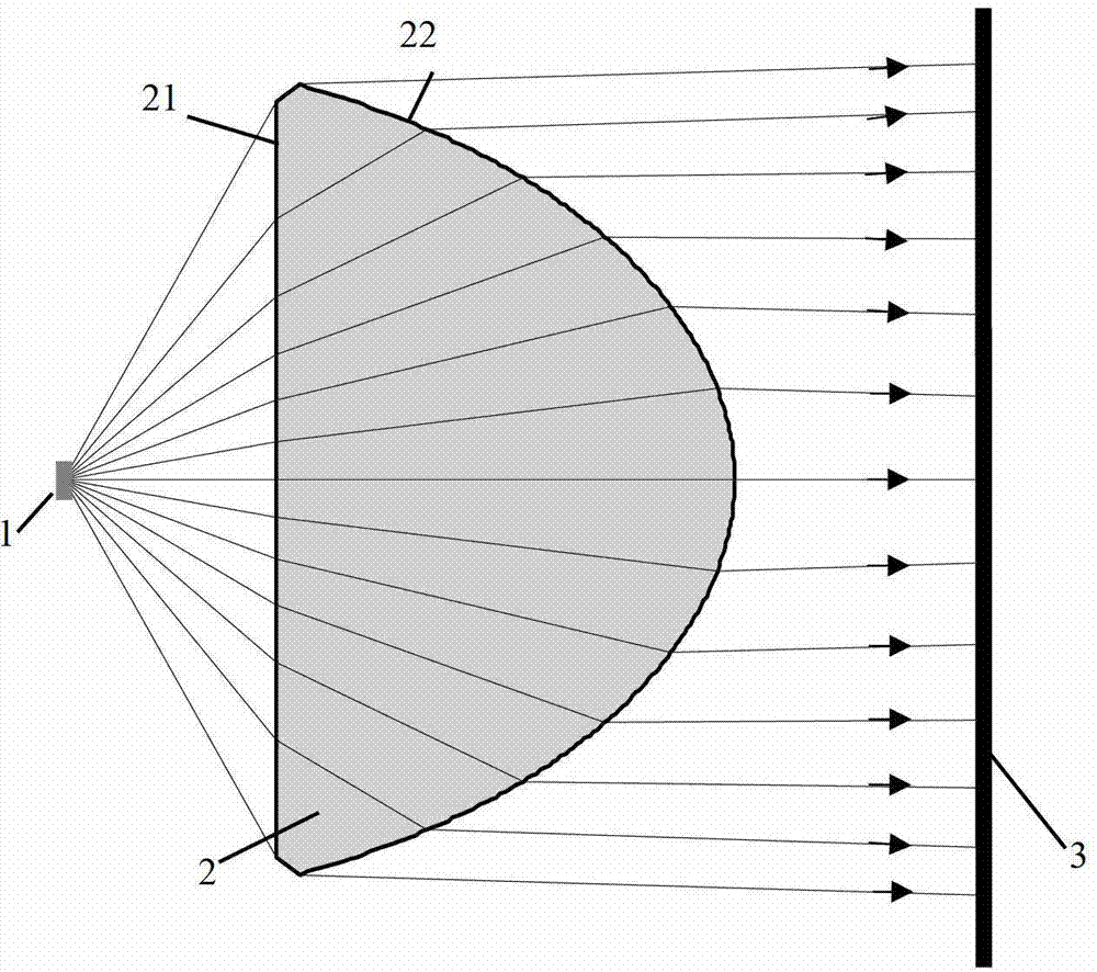
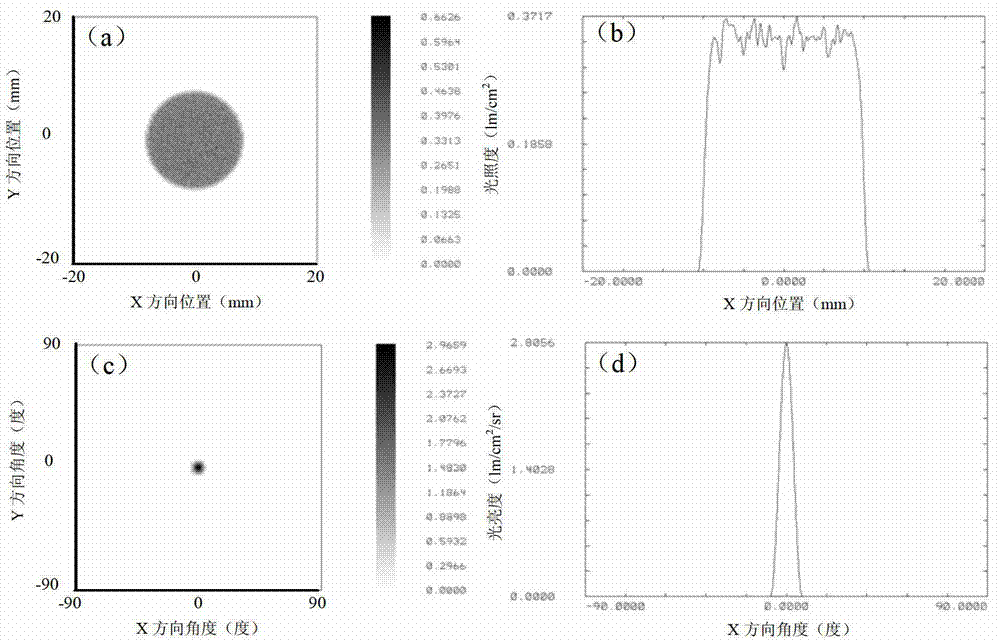
[0029] figure 1 A schematic diagram of the principle of beam shaping realized by the single free-form surface lens proposed by the present invention, including a light source 1 with known luminous characteristics, a single free-form surface lens 2, the front surface of which is set as a plane 21, and the rear surface is a free-form surface 22, and an energy detection surface 3 . The light emitted from the light source 1 is refracted by the front and rear surfaces 21 and 22 of the lens 2 in sequence, and finally reaches the detection surface 3 . The specific surface shape of the free-form surface 22 is jointly determined by the luminous characteristics of the light source 1, the surface shape of the setting surface 21, and various parameters of the specified beam after shaping according to the law of conservation of luminous flux and the law of refraction. What needs to be pointed out here is that the t...

Embodiment 2

[0035] Embodiment 2 A single free-form surface lens with a Fresnel structure realizes beam shaping

[0036] In order to reduce the thickness of the lens, reduce the quality of the lens, reduce material consumption, and shorten the homogenization distance, the lens can adopt a Fresnel structure, such as image 3 (a) and (b) the three-dimensional modeling diagram of its circular aperture. At this time, the thickness of the lens can be less than 3mm. When the light source is a square LED with a light-emitting surface of 1mm×1mm and the luminous intensity distribution is Lambertian, the energy contrast can be obtained on the detection surface 10.5mm away from the light source. about (I max -I min ) / (I max +I min)=0.08 of the light spot, the two-dimensional spatial distribution of energy and the one-dimensional distribution over the center are respectively as follows image 3 (c) and (d). Fresnel structures can be used on either or both of the front and rear surfaces.

[003...

Embodiment 3

[0038] Embodiment 3 Single free-form surface lens array realizes beam shaping

[0039] If multiple lenses are combined in a certain arrangement to form a lens array, and the radiated light of the light source array with the same arrangement is shaped, a larger illumination area can be obtained, or the illumination brightness can be improved, and the uniform light distance can be reduced.

[0040] Figure 4 Schematic diagram of the optical path for beam shaping for a 2×2 lens array arranged in a rectangle. At this time, the aperture of each lens is no longer a circle, but a rectangle. The lens array can shape the light emitted by the array of 2×2LEDs (the light-emitting surface is a square of 1mm×1mm, and the luminous intensity distribution is Lambertian). Figure 5 (a) and (b) respectively show the two-dimensional spatial distribution of the spot energy on the detection plane and the one-dimensional distribution through the center, and the energy contrast is about (I max -I ...


PUM

PropertyMeasurementUnit
Radiusaaaaaaaaaa
Thicknessaaaaaaaaaa

Abstract

The invention provides a single-free-form-surface thick lens with short-distance uniform light effect and an array thereof, and relates to the technical field of secondary optical elements of light sources such as cold cathode fluorescence lamps and LEDs. One surface of the lens is an optionally set curved surface while the other surface of the lens is a free-form surface. In a second optical element, front surfaces and rear surfaces of the lens and the array thereof refract light to control a travelling direction of the light, and thicknesses of the lens and the array determine offset of the light in a radial direction of the lens, so that after emitted light of light sources such as a cold cathode fluorescence lamp and an LED passes the lens, energy on a test surface is specific in spatial distribution, and angle of divergence of reshaped light beams can be partially controlled. The lens and the array thereof can reshape the emitted light of the light sources such as the cold cathode fluorescence lamp and the LED to obtain the light beams excellent in directivity and uniformity. By applying the lens and the array to the fields of backlights of side-disturbance-free uniform lighting and liquid crystal display and the like, lighting effect can be improved remarkably, and uniform light distance is shortened.

Description

technical field [0001] The invention relates to the technical field of secondary optical elements of light sources such as LEDs, and more specifically relates to a single free-form thick lens with a short-distance uniform light effect and an array thereof. Background technique [0002] In the fields of general lighting and public display, traditional light sources (such as cold cathode fluorescent lamps, etc.) and new light sources (such as LEDs, etc.) are widely used. In recent years, with the development of liquid crystal display technology and the maturity of related products, cold cathode fluorescent lamps and LEDs are increasingly used as backlight sources in liquid crystal displays. In particular, LED, as a new generation of light source, has small size, long life, good color rendering, low power consumption, and high luminous efficiency, which is more in line with the current concept of green environmental protection, so its application scope ranges from the initial s...

Claims


Application Information

Patent Timeline
IPC IPC(8): G02B3/06G02B3/08G02B27/09G02B1/00F21V5/04
Inventor 康学亮张晓波曹国威李永平
Owner UNIV OF SCI & TECH OF CHINA
Learn More