
Simulated test device and method for corrosion nearby suction port of downhole oil pump

A simulation test and oil well pump technology, applied in measuring devices, weather resistance/light resistance/corrosion resistance, instruments, etc., can solve the problems of inability to simulate the influence of casing corrosion, different pertinence, and no production string structure

Active Publication Date: 2013-05-22
CHINA PETROCHEM & CHEM JIANGSU OILFIELD BRANCH +1
View PDF10 Cites 2 Cited by
  • Summary
  • Abstract
  • Description
  • Claims
  • Application Information

AI Technical Summary

Problems solved by technology

However, these two types of simulation test devices have different targets. There is no production string structure inside the test device, and it is impossible to simulate the influence of flow velocity, flow state, corrosive gas, etc. near the suction inlet of the oil well downhole pump on casing corrosion.

Method used


Image

  • Simulated test device and method for corrosion nearby suction port of downhole oil pump

Examples


Embodiment 1

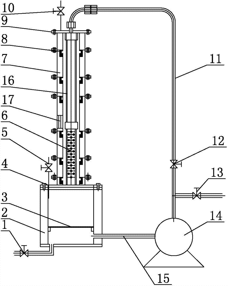
[0021] As shown in the figure, it is a corrosion simulation test device near the suction port of an downhole oil well pump, including a buffer container 4, a liquid discharge valve 1 is provided at the bottom of the buffer container 4, an air filling valve 5 is provided on the buffer container 4, and the inside of the buffer container 4 A heater 2 is provided, and the buffer container 4 is connected to the outlet of the plunger type metering pump 14 through the liquid return pipe 15. The buffer container 4 is provided with a blocking partition 3, and the connection position between the liquid return pipe 15 and the buffer container 4 is located at the Below the partition 3; the top of the buffer container 4 is connected with an upright screen pipe 6, the upper end of the screen pipe 6 is connected with an oil pipe 16, and the upper end of the oil pipe 16 is connected to the inlet of the plunger type metering pump 14 through a high-pressure double-layer hose 11, A shut-off valve...

Embodiment 2

[0024] A corrosion simulation test method near the suction port of an downhole oil well pump, comprising the following steps:

[0025] 1) After weighing multiple test coupons, install them in each sample slot;

[0026] 2) Take the downhole fluid as the test water sample, deoxygenate the test water sample and add it into the buffer container through the liquid filling valve, observe the test water sample from the observation window so that it submerges the screen pipe and the water level is not higher than the top of the observation window;

[0027] 3) Add a certain amount of CO through the gas filling valve 2 , CO 2 The amount of addition and the CO under the formation 2 The content is equivalent, and then, fill the annular space in the main standpipe above the water level with N through the gas filling valve 2 Pressurize to the formation pressure at the pump hang position of the pressure test simulation well;

[0028] 4) The heater heats the test water sample to the formati...


PUM


Abstract

The invention discloses a simulated test device and method for corrosion nearby a suction port of a downhole oil pump, and belongs to the field of oil production test devices. The device comprises a buffer container, wherein an air entrapping valve is arranged on the buffer container, a heater is arranged in the buffer container, the buffer container is connected with an outlet of a plunger type metering pump through a liquid return pipe, the top of the buffer container is connected with a sieve pipe which is arranged uprightly, the upper end of the sieve pipe is connected with an oil pipe, the upper end of the oil pipe is communicated with an inlet of the plunger type metering pump through a high-pressure double-layer hose, the sieve pipe and the oil pipe are arranged in a main vertical pipe, and the main vertical pipe is formed in a manner that a plurality of single vertical pipes with sample grooves are in superimposed connection; an exhaust valve is arranged at the top of the main vertical pipe; the single vertical pipe corresponding to the upper end of the sieve pipe is provided with an observation window; and a cut-off valve is arranged on the high-pressure double-layer hose, and a liquid charging valve is connected between the cut-off valve and the inlet of the plunger type metering pump in a bypass manner. The device can be used for simulating the flowing state of fluid nearby the suction port of the downhole oil pump and researching the corrosion morphologies and regulation of sleeves.

Description

technical field [0001] The invention relates to a test device in oil exploitation, in particular to a corrosion simulation test device. Background technique [0002] The following corrosion simulation test devices are disclosed in the Chinese patent database: First, a simulated accelerated corrosion test device (its application number: 201010516688.0, publication date: June 1, 2011), the main structure includes a test box, a water bath box , resistance wire, ventilation baffle, gas tube, accelerator concentration probe, accelerator inlet tube, test chamber cover, accelerator concentration controller, gas filling controller, electronic temperature controller, accelerator adding tube, accelerator container trough, sample rack, temperature sensor and control keyboard; the control keyboard is arranged with accelerator switch, accelerator speed control knob, accelerator concentration probe switch, accelerator concentration control switch, inflation switch, inflation volume speed ...

Claims


Application Information

Patent Timeline
Patent Type & Authority Applications(China)
IPC IPC(8): G01N17/00
Inventor 彭中楼一珊唐礼骅高斐唐海军寿翔
Owner CHINA PETROCHEM & CHEM JIANGSU OILFIELD BRANCH
Learn More