High-flow high-pressure pneumatic switch valve

A pneumatic switch valve, large flow technology, applied in the direction of valve details, valve devices, engine components, etc., can solve the problems of increasing device instability, precision, strength, high airtight requirements, complex structure, etc., to achieve reduction Complexity and instability, fast and fast opening and closing, and the effect of meeting the requirements of rapid response

Inactive Publication Date: 2013-05-22
NANJING UNIV OF SCI & TECH
View PDF5 Cites 8 Cited by
  • Summary
  • Abstract
  • Description
  • Claims
  • Application Information

AI Technical Summary

Problems solved by technology

But at the same time, this design invention also has certain deficiencies. For example, its structure is relatively complex, including the main valve and the electromagnetic pilot valve. increased device instability

Method used


Image

  • High-flow high-pressure pneumatic switch valve
  • High-flow high-pressure pneumatic switch valve

Examples


Embodiment Construction

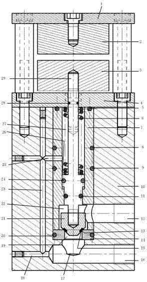
[0013] A high-flow high-pressure pneumatic switching valve of the present invention includes two parts: a main valve and an electromagnet. The electromagnet is located above the main valve and fixed on the main valve by bolts. The electromagnet includes an electromagnet bracket 1, an upper electromagnet 2 and The lower electromagnet 3 (due to the limitation of space, a single electromagnet cannot provide enough suction, and two electromagnets are used here), the upper electromagnet 2 is fixed on the electromagnet bracket 1 by bolts, and the lower electromagnet 3 is fastened to the valve On the core rod 29 protruding from the main valve, there is a counterbore in the center of the upper part of the electromagnet support, which is used to fix the electromagnet. Fixed on the valve cover; the main valve includes valve body 10, valve cover 4, valve sleeve 12, spring 11, valve core seat 14 and valve core part, valve body 10 is used as the bracket part of the main valve, and there is ...


PUM


Abstract

The invention discloses a high-flow high-pressure pneumatic switch valve which comprises a main valve and an electromagnet, wherein the electromagnet is located on the main valve and fixed on the main valve through a bolt. The electromagnet comprises an electromagnet support frame, an upper electromagnet body and a lower electromagnet body. The main valve comprises a valve body, a valve deck, a valve sleeve, a spring, a valve core seat and a valve core, wherein the valve core comprises a cone valve core body with a threaded hole, a valve core rod and a rubber ring. The high-flow high-pressure pneumatic switch valve can solve the problems that when high-pressure gas passes through an ordinary valve, the energy available value of the gas is reduced due to friction and the like, and the amount of the gas flowing through the ordinary valve is quite small, and can improve the energy utilization rate of a device in which compressed air is used for storing and supplying energy and the like; and meanwhile, the high-flow high-pressure pneumatic switch valve is simple in structure and is only composed of the electromagnet and the main valve, so that complexity and instability of the device are reduced, when the high-flow high-pressure pneumatic switch valve needs to be opened or closed, just the electromagnet needs to be powered on or powered off, the electromagnet responds fast, and therefore the response speed of opening and closing the valve is extremely high, the effect that the high-flow high-pressure pneumatic switch valve is opened and closed rapidly can be achieved, and the high-flow high-pressure pneumatic switch valve can meet the requirement on fast response of pneumatic automobiles and other vehicles.

Description

technical field [0001] The invention belongs to the field of pneumatic pressure, in particular to a large-flow high-pressure pneumatic switching valve. Background technique [0002] With the development of automation technology, pneumatic technology is gradually widely used in various fields. In the pneumatic system, the realization of various functions is mainly through the control of various pneumatic valves, such as reversing valves, pressure reducing valves, throttle valves, etc. Usually, the high-pressure gas in the gas tank enters the pneumatic circuit after being adjusted to a suitable working pressure by the pressure-relief valve. The larger the span, the more energy is lost. [0003] In some special occasions, in order to store more energy, the pressure of the gas tank is relatively high (greater than 23MPa), and the working pressure is relatively low. If the throttling and decompression method is used, a large amount of energy will be lost. In order to overcome ...

Claims


Application Information

Patent Timeline
Patent Type & Authority Applications(China)
IPC IPC(8): F16K31/12F16K31/06
Inventor 潘孝斌李从祥谈乐斌王文彪彭海萍
Owner NANJING UNIV OF SCI & TECH
Why Eureka
Try Eureka