A stepped blade hydraulic machine

A hydraulic machinery and vane-type technology, applied in the field of hydraulic machinery, to achieve the effect of eliminating reactive power loss, reducing wear and tear, and good product manufacturability

Active Publication Date: 2015-11-18
胡阳
View PDF10 Cites 0 Cited by
  • Summary
  • Abstract
  • Description
  • Claims
  • Application Information

AI Technical Summary

Problems solved by technology

[0012] The purpose of the present invention is to solve the problem that the vane-type hydraulic machinery in the prior art still needs energy transmission in the non-working stage, and cannot avoid reactive power loss after unloading, and reduce energy loss. The pressure is balanced, the work is stable, the wear is small, and it can realize idling, avoid the reactive power loss after unloading, and reduce the energy loss of the stepped blade hydraulic machinery

Method used


Image

  • A stepped blade hydraulic machine
  • A stepped blade hydraulic machine
  • A stepped blade hydraulic machine

Examples


Embodiment 1

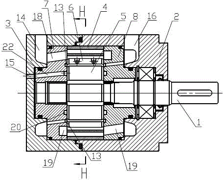
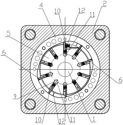
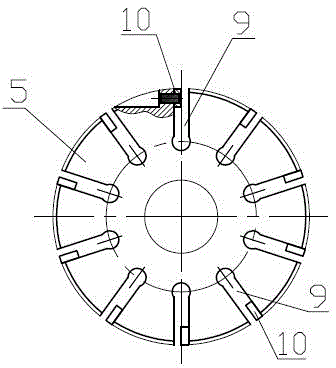
[0039] exist figure 1 , figure 2 In the shown embodiment, a stepped blade hydraulic machine includes a shaft 1, a front housing 2, a rear housing 3, a stator 4 arranged inside the front housing 2 and the rear housing 3, a rotor 5, and blades 6 , oil inlet oil distribution plate 7 and oil outlet oil distribution plate 8, the joint of the front housing 2 and the oil outlet oil distribution pan 8, the joint of the rear housing 3 and the oil inlet oil distribution pan 8, and the front housing 2 A sealing device is provided at the joints with the rear housing 3, a bearing and a shaft sealing device are provided between the shaft 1 and the front housing 2, and the shaft 1 and the rotor 5 are connected by a key. In this embodiment, ten rotor slots 9 are uniformly arranged on the rotor 5 (see image 3 ), the number of rotor slots 9 can also be set to twelve or other numbers according to needs, the inside of the rotor slot 9 is provided with blades 6, the bottom of the rotor slot 9 ...

Embodiment 2

[0043] A stepped blade type hydraulic machine, the structure of which is basically the same as that of Embodiment 1, the difference is that in this embodiment, the cross section of the blade and the rotor groove is set as a T-shaped structure, the rotor groove is an integrated structure, and the blade is also an integrated structure , the front housing 2 and the rear housing 3 are also provided with external inlets, so that the external liquid can be directly introduced into the control chamber from the external inlets, so as to realize the balance of the pressure in the top chamber and the bottom chamber of the blade. Of course, at this time The control cavity is not connected to the inlet or outlet cavity at the top of the blade, nor is it connected to the bottom cavity. The purpose of setting the external inlet is to allow the chamber oil inside the control cavity to be directly introduced from the outside and connected to the work On the main engine, when the pump or motor ...


PUM


Abstract

The invention discloses step blade type hydraulic machinery which comprises a shaft, a front shell, a rear shell, and a stator, a rotor, blades, an inlet oil distribution disc and an outlet oil distribution disc, which are arranged inside the front shell and the rear shell, wherein a plurality of rotor grooves are uniformly formed in the rotor, the blades are movably arranged in the rotor grooves, the thickness of the roots of the blades is more than that of the tops of the blades, bottom cavities are formed between the blades and the bottoms of the rotor grooves, control cavities are formed between the blades and the walls of the rotor grooves, and kidney slots are respectively formed in the inlet oil distribution disc and the outlet oil distribution disc and correspond to the control cavities. The step blade type hydraulic machinery works stably and is little in abrasion because the pressures of the blades on the inner surface of the stator are balanced, and is capable of realizing idling and avoiding reactive loss after unloading so as to ensure low energy loss.

Description

technical field [0001] The invention relates to the technical field of hydraulic machinery, in particular to a stepped blade hydraulic machinery. Background technique [0002] The vane hydraulic pump or motor is small in size, small in moment of inertia, and sensitive in action. It is suitable for occasions with high commutation frequency, but the leakage is large and unstable at low speed. Therefore, vane hydraulic motors are generally used in occasions with high speed, small torque and sensitive action requirements. For traditional hydraulic pumps or motors, in order to ensure that the vane hydraulic motor can start normally after the pressure oil is introduced, the top of the vane must be in close contact with the inner surface of the stator to ensure a good seal, so pre-tension springs are provided at the root of the vane , but in this traditional hydraulic motor and pump, since the blade root is provided with a preload spring, the top of the blade is always in close co...

Claims


Application Information

Patent Timeline
Patent Type & Authority Patents(China)
IPC IPC(8): F04C2/344F04C15/00
Inventor 胡凯王新彪于明镇宋仙友
Owner 胡阳
Why Eureka
Try Eureka