
Roll shaft type metal shock-insulating supporting seat

A technology of seismic isolation bearings and roller shafts, which is applied in the direction of earthquake resistance, building components, construction, etc., can solve problems such as failure of seismic isolation bearings, prolonging the equivalent period, and weak tensile strength, so as to protect the upper structure and structure The effect of period extension and obvious vibration isolation effect

Inactive Publication Date: 2013-05-22
王涛 +2
View PDF4 Cites 10 Cited by
  • Summary
  • Abstract
  • Description
  • Claims
  • Application Information

AI Technical Summary

Problems solved by technology

However, when the laminated rubber bearing is under tension, the steel plate no longer acts as a restraint, and the axial tensile stiffness of the laminated rubber bearing is greatly reduced. In high-rise buildings, due to the large aspect ratio of the structure, under earthquake The overturning action of the structure may cause the bearing to be in tension, and the tensile strength of the laminated rubber bearing is not high, so it is difficult to apply in high-rise buildings
[0004] The friction pendulum bearing uses the sliding of the slider in the smooth curved surface to play the role of shock isolation. The curved surface is generally made of polytetrafluoroethylene material with corrosion resistance and small friction coefficient. Due to the low friction force, the equivalent period of the friction pendulum structure is adopted. It can be extended a lot. At the same time, the concave surface of the curved surface faces upward, and the slider slides in the concave surface. During the movement, the structure is lifted, and part of the kinetic energy is converted into the potential energy of the structure, which gradually disappears as the earthquake action decreases, and finally the structure returns to its original position. Friction pendulum has been paid attention to in recent years, but there is also the problem of weak tensile strength. Under large displacement, the upper cover plate will be separated from the slider, which will cause the vibration isolation support to fail.
[0005] Regardless of the seismic isolation structure using laminated rubber bearings or friction pendulum bearings, because the bearings have low torsional stiffness, when designing the structure, the center of mass of the structure should be as close as possible to the center of stiffness of the isolation layer. In order to reduce the overall torsion of the structure during earthquakes, this feature also limits the application of seismic isolation bearings in special-shaped structures

Method used


Image

  • Roll shaft type metal shock-insulating supporting seat
  • Roll shaft type metal shock-insulating supporting seat
  • Roll shaft type metal shock-insulating supporting seat

Examples


Embodiment 1

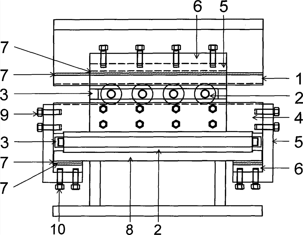
[0038] figure 1 It is a schematic diagram of the structure of this embodiment. This embodiment consists of an upper connecting plate 1, a roller shaft 2, a roller frame 3, an intermediate end plate 4, an L-shaped tensile connecting plate 5, a pre-tightening pad 6, a polytetrafluoroethylene plate 7, and a lower connecting plate 8 , 9 friction-type high-strength bolts, 10 high-strength tensile bolts. During assembly, a plurality of roller shafts 2 are installed in the roller frame 3 earlier, and the cylindrical supports 13 at both ends of the rollers extend into the cylindrical holes 14 of the roller frame, and the positions where the two contact are lubricated with lubricant. The roller set is placed in the rolling groove 12 of the middle end plate 4 . The middle end plate 4 and the upper connecting plate 1 are fixed through the L-shaped tensile connecting plate 5, and the friction type high-strength bolts 9 are used for the connection. The side of the L-shaped tensile connec...

Embodiment 2

[0048] Figure 10 It is the specific structure schematic diagram of this embodiment. Balls 20 are set between the upper connecting plate 1, the lower connecting plate 8 and the pre-tightening force backing plate 6, and the ball rolling grooves 21, 22 are set on the upper connecting plate 1, the lower connecting plate 8 and the pre-tightening force backing plate 6. The rolling of the ball replaces the sliding of the PTFE plate, which further reduces the friction force and horizontal stiffness during tension, and can be used for structures with lower rigidity requirements during tension. The diameter and number of balls can be set according to the tensile bearing capacity. fixed, for a structure with a large tensile bearing capacity, the ball can also be replaced by a roller shaft. At this time, the length of the roller shaft is smaller than the length of the pressure roller shaft. The effect of the compressive bearing capacity is much larger than the tensile bearing capacity, ...

Embodiment 3

[0051] Figure 12 It is the specific structure schematic diagram of this embodiment. Paste polytetrafluoroethylene plates 23 on the contact surfaces of the upper and lower connecting plates 1, 8 and the middle end plate 4, and use the sliding between the polytetrafluoroethylene plates to reduce the seismic force and achieve the effect of shock isolation. This embodiment is especially suitable In the case of small installation space and high bearing capacity. Since the sliding friction between the PTFE plates is used for shock isolation, the friction coefficient is larger than the rolling friction of the roller shaft, and the shock isolation effect is slightly worse. However, due to the pressure or tension on the contact surface, its vertical bearing capacity Much bigger. Other structures of this embodiment are the same as those of Embodiment 1.

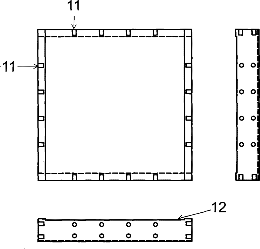
[0052] Figure 13 It is a schematic diagram of the polytetrafluoroethylene plate of the present embodiment.


PUM


Abstract

The invention relates to a roll shaft type metal shock-insulating supporting seat which is used for base shock insulation in house buildings. The roll shaft type metal shock-insulating supporting seat comprises an upper connection plate, a roll shaft, a roll shaft frame, a middle end plate, an L-shaped pull-resisting connection plate, a pretightening force base plate, a lower connection plate, friction type high-strength bolts and high-strength pull-resisting bolts. The roll shaft type metal shock-insulating supporting seat can be used as a base shock-insulating element to be applied to low-rise building structures, high-rise building structures and super high-rise building structures. When the earthquake action is too large, and the shock-insulating supporting seat is enabled to bear pull force, the L-shaped pull-resisting connection plate and the high-strength pull-resisting bolts play roles in pull resistance. Meanwhile, polyfluotetraethylene plates with extra-low friction coefficient slide between each other, and the roll shaft type metal shock-insulating supporting seat still can play the shock-insulating role when the roll shaft type metal shock-insulating supporting seat is pulled.

Description

(1) Technical field [0001] The invention belongs to the technical field of structural engineering shock isolation, and relates to a shock isolation bearing device which utilizes roller shaft rolling and polytetrafluoroethylene plate friction sliding to reduce earthquake input energy. (2) Background technology [0002] Base isolation technology is to artificially set a soft layer between the superstructure of the building and the foundation. When an earthquake strikes, the high-frequency components that play a leading role cannot pass through the soft layer and enter the superstructure, thereby protecting the superstructure. This soft layer is also known as shock-absorbing layer. Due to the seismic isolation effect of the seismic isolation layer, the structural response of the upper structure is only equivalent to 1 / 4-1 / 8 of that without isolation, which not only achieves the purpose of reducing the damage to the upper structure caused by the earthquake, but also improves the...

Claims


Application Information

Patent Timeline
IPC IPC(8): E04B1/36E04B1/98
Inventor 王涛丁路通滕睿
Owner 王涛
Learn More