Hydraulic pressure rubber cutting machine and use method thereof
A glue cutting machine and hydraulic technology, applied in metal processing and other directions, can solve the problems of multiple cutting and uneven cutting glue blocks, and achieve the effect of improving the degree of cutting, uniform viscous flow time, and simplifying the process flow.
- Summary
- Abstract
- Description
- Claims
- Application Information
AI Technical Summary
Problems solved by technology
Method used
Image
Examples
Embodiment 1
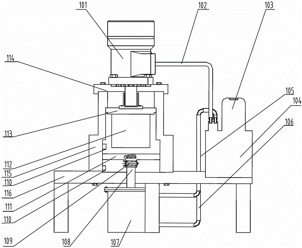
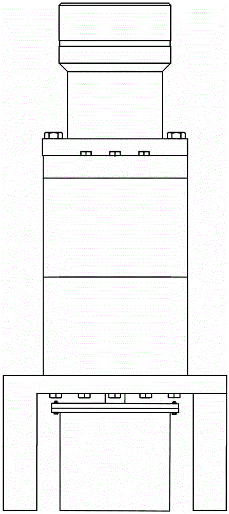
[0032] Example 1, such as Figure 1 to Figure 2 As shown, a hydraulic rubber cutting machine includes a frame on which a hydraulic drive system and a hydraulic control system are mounted, as well as a rubber cutter 112 driven by the hydraulic control system and the hydraulic drive system, and a beam 114 on the frame Fixedly connected to the hydraulic drive system, the center of the upper beam 114 has a round hole to accommodate the plunger rod of the hydraulic drive system; the hydraulic control system includes the motor 103 and the hydraulic station 104, and the motor 103 and the hydraulic station 104 are connected to the hydraulic drive system through the oil pipeline 102; The knife 112 is assembled on the knife rest 113, and the knife rest 113 is connected to the output shaft of the hydraulic drive system. The knife rest 113 is equipped with an array of rubber cutting knives 112; The rubber cutting disc 111 for cutting rubber blocks; the hydraulic control system and the hyd...
Embodiment 2
[0037] Example 2, such as Figure 1 to Figure 2 As shown, a hydraulic rubber cutting machine includes a frame on which a hydraulic drive system and a hydraulic control system are mounted, as well as a rubber cutter 112 driven by the hydraulic control system and the hydraulic drive system, and a beam 114 on the frame Fixedly connected to the hydraulic drive system, the center of the upper beam 114 has a round hole to accommodate the plunger rod of the hydraulic drive system; the hydraulic control system includes the motor 103 and the hydraulic station 104, and the motor 103 and the hydraulic station 104 are connected to the hydraulic drive system through the oil pipeline 102; The knife 112 is assembled on the knife rest 113, and the knife rest 113 is connected to the output shaft of the hydraulic drive system. The knife rest 113 is equipped with an array of rubber cutting knives 112; The rubber cutting disc 111 for cutting rubber blocks; the hydraulic control system and the hyd...
Embodiment 3
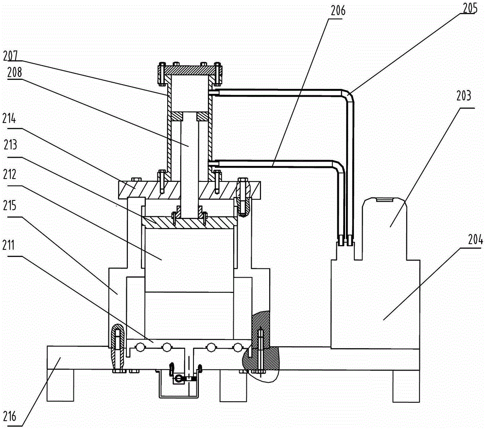
[0042] Example 3, such as Figure 3 to Figure 4 As shown, a hydraulic rubber cutter includes a frame on which a hydraulic drive system and a hydraulic control system are mounted, as well as a rubber cutter 212 driven by the hydraulic control system and the hydraulic drive system, and a beam 214 on the frame Fixedly connected to the hydraulic drive system, the center of the upper beam 214 has a round hole to accommodate the plunger rod of the hydraulic drive system; the hydraulic control system includes the motor 203 and the hydraulic station 204, the motor 203 and the hydraulic station 204 are connected to the hydraulic drive system through the oil pipeline; the rubber cutter 212 is assembled on the knife frame 213, and the knife frame 213 is connected to the output shaft of the hydraulic drive system. The knife frame 213 is equipped with an array of rubber cutters 212; the lower end 216 of the frame is connected to the position corresponding to the rubber cutter 212 to carry t...
PUM
 Abstract
Description
Claims
Application Information
 - R&D
- Intellectual Property
- Life Sciences
- Materials
- Tech Scout
- Unparalleled Data Quality
- Higher Quality Content
- 60% Fewer Hallucinations
Browse by: Latest US Patents, China's latest patents, Technical Efficacy Thesaurus, Application Domain, Technology Topic, Popular Technical Reports.
© 2025 PatSnap. All rights reserved.Legal|Privacy policy|Modern Slavery Act Transparency Statement|Sitemap|About US| Contact US: help@patsnap.com


