Eureka AIR delivers breakthrough ideas for toughest innovation challenges, trusted by R&D personnel around the world.

Motor winding and electronic power switch combination assembly capable of switching output state

A power electronic switch, output state technology, applied in the shape/style/structure of winding conductors, electrical program control, program control in sequence/logic controllers, etc., can solve the problem of limited motor operating speed range and low starting torque , can not have too high no-load speed and other problems

Inactive Publication Date: 2013-05-15
J D COMPONENTS CO LTD
View PDF9 Cites 9 Cited by
  • Summary
  • Abstract
  • Description
  • Claims
  • Application Information

AI Technical Summary

Problems solved by technology

[0003] However, for the motor windings of the aforementioned Y-type connection mode, if the motor is expected to have a higher no-load speed when running, its starting torque will be lower. On the contrary, if the driven motor has a higher starting torque, it will not be able to have too high No-load speed, so the motor's operating speed range is limited

Method used


Image

  • Motor winding and electronic power switch combination assembly capable of switching output state
  • Motor winding and electronic power switch combination assembly capable of switching output state
  • Motor winding and electronic power switch combination assembly capable of switching output state

Examples


Embodiment Construction

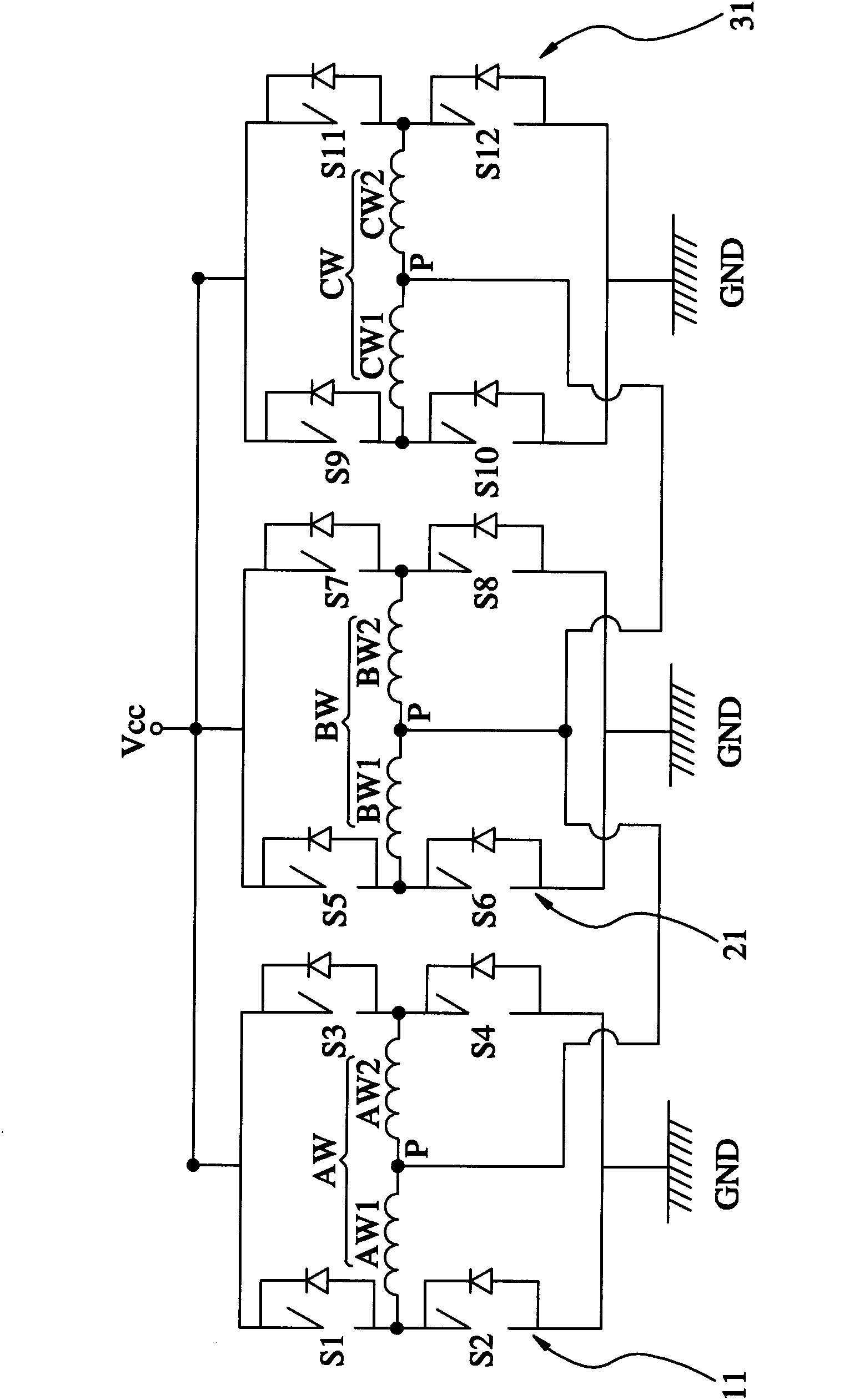
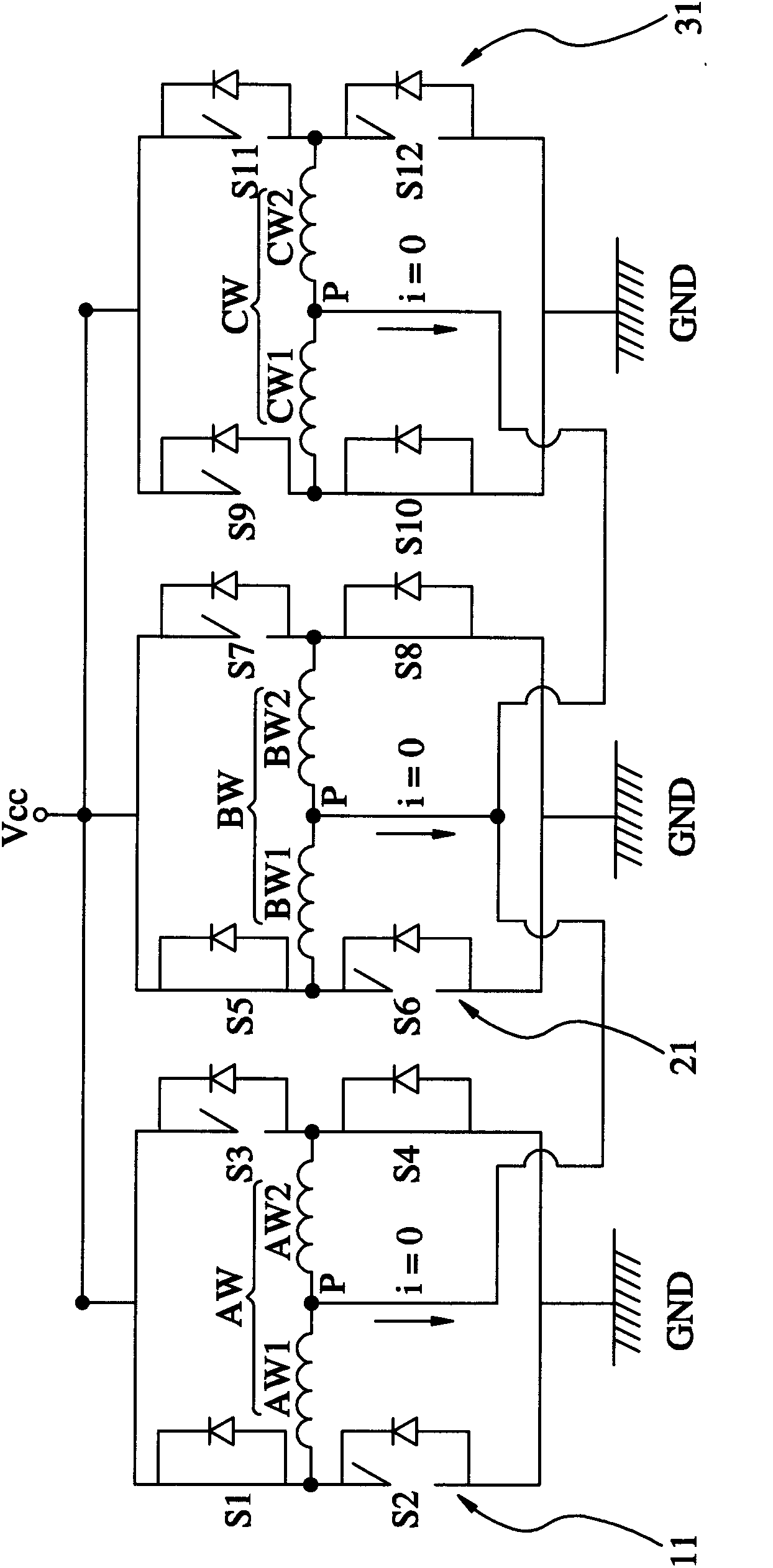
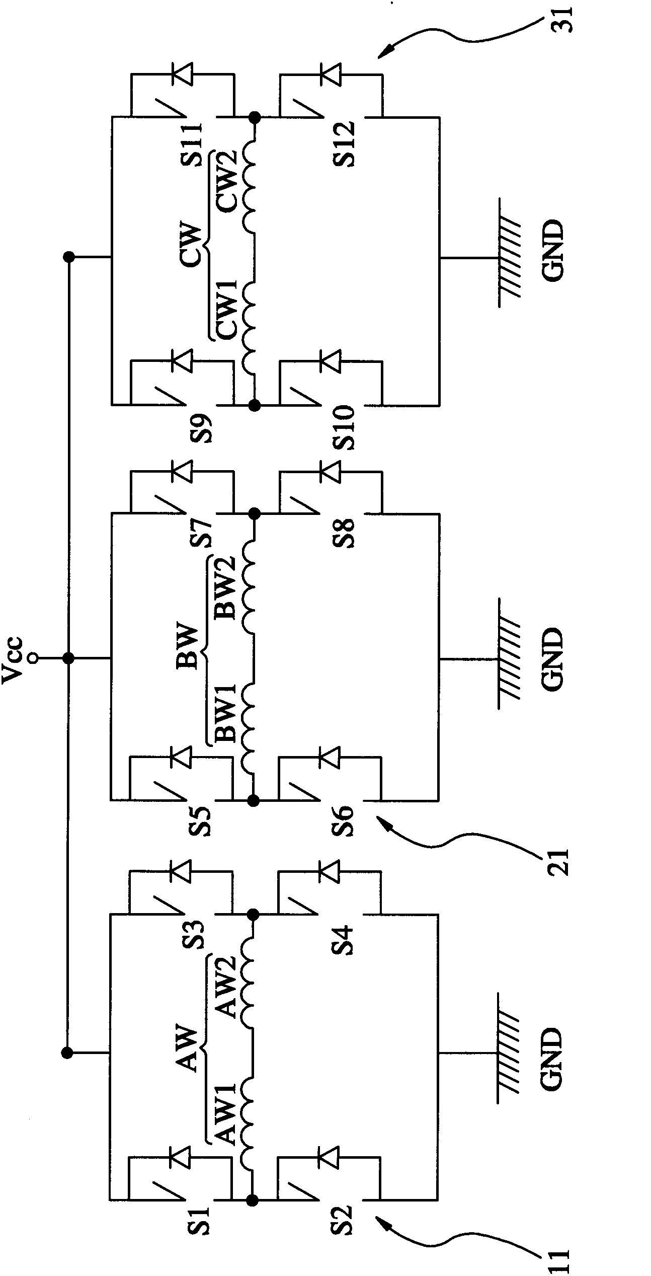
[0018] like figure 1 As shown, a combination assembly 10 of a motor winding and a power electronic switch that can switch the output state provided by a preferred embodiment of the present invention is mainly composed of a first winding AW, a first switch group 11, a first Two windings BW, a second switch group 21, a third winding CW, a third switch group 31 and a mode control means (not shown), wherein:

[0019] The first winding AW is divided into a first upper half winding AW1 and a first lower half winding AW2, the first upper half winding AW1 and the first lower half winding AW2 are connected to a common point P at one end, and The first upper half winding AW1 is symmetrical to the first lower half winding AW2. In this embodiment, the symmetry of the windings refers to the fact that the upper half winding and the lower half winding have the same number of turns as an example, but the number of turns is similar. It is also within the allowable range, that is, the aforesa...


PUM


Abstract

A motor winding and electronic power switch combination assembly capable of switching output state comprises a first winding, a first switch set, a second winding, a second switch set, a third winding, a third switch set and a mode control method, wherein the first winding is composed of a first upper haft winding and a first lower half winding, the first upper half winding and the first lower half winding are connected on a common connection point, the first switch set is provided with four electronic power switches and is connected with the first winding in an electric mode, the second winding is composed of a second upper half winding and a second lower half winding, the second upper half winding and the second lower half winding are connected on the common connection point, the second switch set is provided with four electronic power switches and is connected with the second winding in an electric mode, the third winding is composed of a third upper half winding and a third lower half winding, the third upper half winding and the third lower half winding are connected on the common connection point, the third switch set is provided with four electronic power switches and is connected with the third winding in an electric mode, the mode control method is used for controlling the power-on or power-off of the electronic power switches, and then an H type driving mode or a Y type driving mode is formed, and effect of output state switching is achieved.

Description

technical field [0001] The present invention is related to the driving technology of the motor, in particular to a combined assembly of the motor winding and the power electronic switch which can switch the output state. Background technique [0002] Known motor windings such as Figure 9 As shown, it is connected in a Y-shaped manner with three windings AW, BW, and CW. The three windings correspond to phase A, phase B, and phase C respectively, and through six power electronic switches T1, T2, T3, T4, The on and off states of T5 and T6 are used to change the current on each winding, thereby achieving the purpose of driving the three-phase motor. [0003] However, for the motor windings of the aforementioned Y-type connection mode, if the motor is expected to have a higher no-load speed when running, then its starting torque will be lower. On the contrary, if the driven motor has a higher starting torque, it will not be able to have too high No-load speed, so the motor's op...

Claims


Application Information

Patent Timeline
IPC IPC(8): H02K3/04G05B19/04
Inventor 王世杰李元奎吴梅豪
Owner J D COMPONENTS CO LTD
Why Eureka
Eureka Blog
Learn More