Optical touch control panel and brightness control method thereof

A brightness control and optical technology, which is applied in character and pattern recognition, instruments, electrical digital data processing, etc., can solve problems such as glare, light source loss, usable time of portable electronic devices, and strong users

Active Publication Date: 2013-05-15
AU OPTRONICS CORP
View PDF9 Cites 5 Cited by
  • Summary
  • Abstract
  • Description
  • Claims
  • Application Information

AI Technical Summary

Problems solved by technology

[0004] However, such a strong light source is not needed to achieve the touch function, so the current optical touch panel with scanning function will waste a lot of power when it is not scanning
What's more, if the touch panel is configured on a portable electronic device, the power consumption of the touch panel will affect the...

Method used


Image

  • Optical touch control panel and brightness control method thereof
  • Optical touch control panel and brightness control method thereof
  • Optical touch control panel and brightness control method thereof

Examples


Embodiment Construction

[0071] The detailed features and advantages of the present invention are described in detail below in the embodiments, the content of which is sufficient for those of ordinary skill to understand the technical content of the present invention and implement it accordingly. Objects and advantages associated with the present invention can be readily understood by those of ordinary skill.

[0072] The present invention provides an optical touch pad (optical touch pad) and its brightness control method, wherein the optical touch pad is a single optical touch pad with both touch function and scanning function.

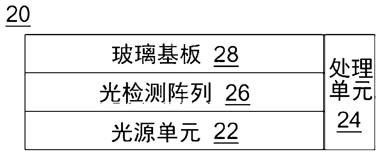
[0073] Please refer to" Figure 1A "as well as" Figure 1B ", which are schematic diagrams of optical touch panels of different implementation examples. The optical touch panel 20 may include a light source unit 22 , a processing unit 24 and a light detection array 26 . The optical touch panel 20 may not have a display function, or may have a display function, which is not...


PUM


Abstract

An optical touch control panel comprises a light source unit and a processing unit, wherein the processing unit is used to perform the brightness control method of the optical touch control panel. The brightness control method for the optical touch control panel comprises the following steps of: under a touch control mode, making a light source unit of the optical touch control panel emit light with a first light source strength, responding to a switch condition to switch to a scanning mode, and making the light source unit emit light with a second light source strength.

Description

technical field [0001] The invention relates to an optical touch panel and its brightness control method, in particular to an optical touch panel with multiple modes and its brightness control method. Background technique [0002] In recent years, touch panels or touch screens with touch sensors have been widely developed and used, and the touch sensors can be resistive, capacitive or optical according to their operating principles. Among them, the optical touch sensor can configure the light detector on the touch panel, so that the display screen can be used as an input area at the same time. In a touch panel with an optical touch sensor, there is a light detector and a light source capable of emitting light from the touch panel. When there is an object on the touch panel, the light emitted by the light source is blocked by the object in the area where the object exists, and part of the light is reflected by the object and then enters the light detector. By sensing the re...

Claims


Application Information

Patent Timeline
IPC IPC(8): G06F3/042
CPCG06F3/0421G06F3/0425H04N1/195G06F3/041661G06V40/1318G06F3/0304
Inventor 郑造时章钧郭柏佑卓恩宗张钧杰
Owner AU OPTRONICS CORP
Why Eureka
Try Eureka