
High-gain and high-power millimeter wave power amplifier

A power amplifier and high-power technology, applied in the direction of power amplifiers, DC-coupled DC amplifiers, differential amplifiers, etc., can solve the problems of large loss, large area, and reduced area, so as to reduce loss, small circuit area, and overcome instability Effect

Inactive Publication Date: 2013-05-08
SOUTHEAST UNIV
View PDF4 Cites 30 Cited by
  • Summary
  • Abstract
  • Description
  • Claims
  • Application Information

AI Technical Summary

Problems solved by technology

The disadvantage of the first solution is large loss and large area; the second solution can reduce the area, but the loss is still large

Method used


Image

  • High-gain and high-power millimeter wave power amplifier
  • High-gain and high-power millimeter wave power amplifier
  • High-gain and high-power millimeter wave power amplifier

Examples


Embodiment Construction

[0028] In order to make the technical means, creative features, goals and effects achieved by the present invention easy to understand, the present invention will be further described below in conjunction with specific embodiments.

[0029] Such as figure 1 As shown, the high-gain and high-power millimeter-wave power amplifier of the present invention includes an input power divider Tin, a first-stage pseudo-differential amplifier A1, a second-stage pseudo-differential amplifier A2, a third-stage pseudo-differential amplifier A3, and a first-stage pseudo-differential amplifier A3. An interstage matching network MN1, a second stage interstage matching network MN2, and an output power combiner Tout. The input end of the input power divider Tin is connected to the signal source Vs, and the signal is input from the input port of the input power divider Tin, and converted into two differential signal outputs. The output of the input power divider Tin is connected to the input term...


PUM


Abstract

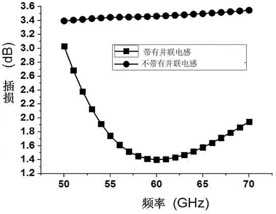
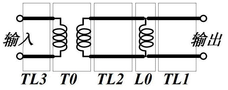
The invention discloses a high-gain and high-power millimeter wave power amplifier which comprises a four-way three-level pseudo differential amplifier. The pseudo differential amplifier adopts capacitance neutralization technology. An input-output circuit adopts a transformer of 2:4 to complete power distribution and power synthesis. The transformer, a transmission line and a shunt inductor are adopted among levels of the amplifier to carry out impedance matching. The pseudo differential amplifier uses the capacitance neutralization technology and improves stability of the circuit and gain. Due to the fact that the shunt inductor is added in a matching network formed by the common transmission line and the transformer, loss among the levels of the matching network can be reduced. The high-gain and high-power millimeter wave power amplifier uses the transformer of 2:4, can achieve four-way power synthesis and impedance matching, greatly improves output power, and decreases the area at the same time.

Description

technical field [0001] The invention relates to a power amplifier, in particular to a millimeter-wave power amplifier with high gain and high power in a submicron CMOS process. However, it should be noted that the power amplifier involved in this invention can be implemented in other processes. Background technique [0002] At present, since the power amplifier of the CMOS process has a high degree of integration and is easy to combine with the baseband, more and more attention has been paid to it. However, power amplifiers in CMOS technology have several challenges. [0003] First, at high frequencies, the presence of Miller capacitance affects the stability of the transistor. In order to make the transistor meet the stability condition, the existing technology generally adopts: a) resistance-capacitance feedback circuit; b) input series resistance or parallel resistance. But both techniques have the disadvantage of reducing the maximum available power gain of the transi...

Claims


Application Information

Patent Timeline
IPC IPC(8): H03F3/20H03F3/45
Inventor 李连鸣崔铁军陈林辉
Owner SOUTHEAST UNIV
Learn More