Electrical connector and electrical connector assembly

An electrical connector and connector technology, which is applied to the parts, connection, and fixed connection of the connection device, can solve the problems of solder material, flux spatter, productivity reduction, and increase the emission of electromagnetic wave noise, and increase the number of manufacturing processes. , No damage to productivity, good electromagnetic shielding effect

Active Publication Date: 2015-05-20
DAIICHI SEIKO CO LTD
View PDF6 Cites 0 Cited by
  • Summary
  • Abstract
  • Description
  • Claims
  • Application Information

AI Technical Summary

Problems solved by technology

[0004] However, the conventional electrical connector is constructed so that only the outer surface of the main body box is covered with a conductive shell, and the tip portion of the above-mentioned conductive contact (conductive terminal), more specifically, the connection portion with the main wiring board, is not Covered by a conductive shell but exposed to the outside
Therefore, especially as the frequency of transmission signals has increased in recent years, the influence of electromagnetic wave noise from the outside cannot be ignored at the connection portion to the main wiring board, and the possibility of electromagnetic noise radiation from the connection portion to the outside has also increased.
[0005] In the prior art, there is a technology of pasting a conductive tape on the connection part of the conductive contact and the main wiring board, or extending the conductive shell to cover the part. However, when using the conductive tape, due to the additional There is a tendency to reduce productivity because of the time-consuming work process of sticking conductive tape.
Moreover, when the conductive case is extended and covered, there is a problem that the connecting portion of the conductive contact and the main wiring board cannot be confirmed by visual inspection or image inspection, and it is difficult to check and confirm whether the connection is flawless or not. Obstacles
[0006] In addition, in the existing electrical connectors, a plurality of coaxial cables arranged in a multi-pole shape are connected to each other by jumping ground with a ground rod, and sometimes a part of the conductive shell is soldered to the ground rod, and when the conductive shell When soldering the ground rod in this way, the flux contained in the solder material is rapidly foamed due to the heating of the solder material, and the solder material and flux splash and adhere to parts other than the original connection part, such as the conductive contact. contact part, electrical barriers may occur

Method used


Image

  • Electrical connector and electrical connector assembly
  • Electrical connector and electrical connector assembly
  • Electrical connector and electrical connector assembly

Examples


Embodiment Construction

[0032] Embodiments in which the present invention is applied to an electrical connector for connecting a plurality of coaxial cables to the side of a printed wiring board will be described in detail below with reference to the drawings.

[0033] (Outline of the overall structure of the electrical connector assembly)

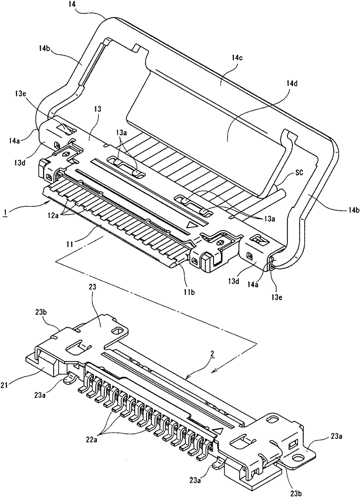
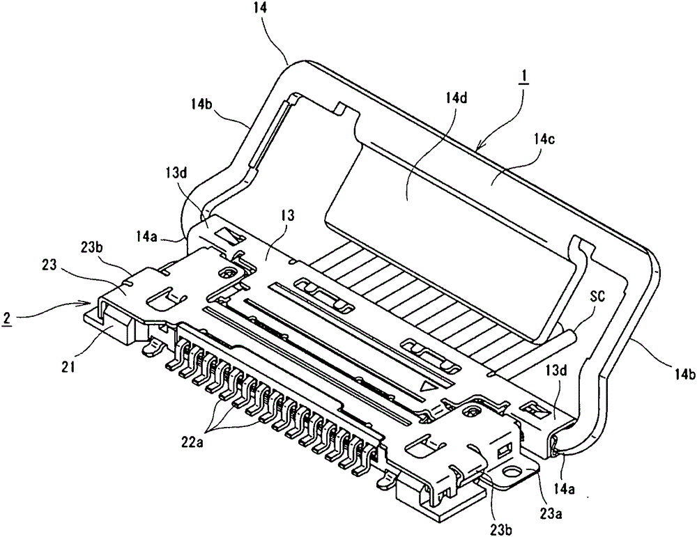
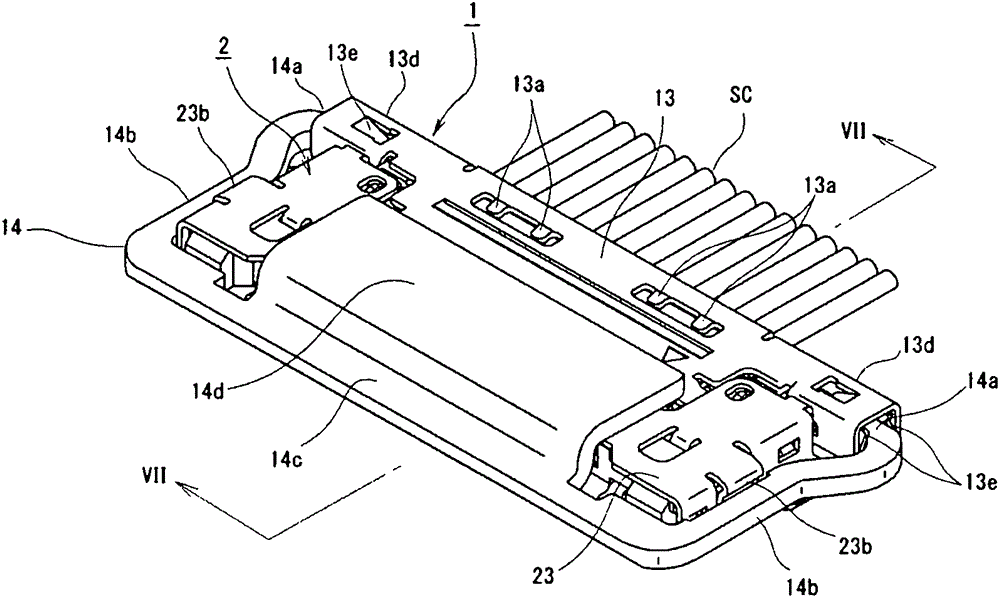
[0034] first, Figure 1 to Figure 7 The shown electrical connector assembly according to the first embodiment of the present invention is composed of a plug connector 1 to which a terminal portion of a coaxial cable SC is connected, and a receptacle connector mounted on a main printed wiring board B. 2 horizontal fitting type electrical connectors, as the first connector plug connector 1 relative to the mating object, that is, as the second connector receptacle connector 2 is arranged in the substantially horizontal direction, from this state to connect the above-mentioned plug device 1 moves closely along the surface of the main printed wiring board B, so that ...


PUM


Abstract

The invention discloses an electrical connector and an electrical connector assembly. Electromagnetic shielding relating to a conductive contact (22) and a connection part (22a) of a main distributing basilar plate (B) can be well conducted without loss of productivity by the electrical connector and the electrical connector assembly. The electrical connector and the electrical connector assembly are turned from an embedding open position to an embedding function position on an embedding maintaining element (14) which is used for maintaining the embedding states of connectors (1 and 2), when the embedding maintaining element (14) turns to the embedding function position, an other covering connector (2) and an electric conduction covering part (14d) of the connection portion (22a) of the main distributing basilar plate (B) are set to cover the connection portion (22a), through the embedding of the two connectors (1 and 2), the portion is electromagnetic masked (shielded) at the same time, and thereby the manufacturing process cannot be increased, the connection states of the conductive contact (22) and the connection part (22a) of the main distributing basilar plate (B) are confirmed well before the embedding maintaining element (14) is turned to the embedding function position by a child.

Description

technical field [0001] The present invention relates to an electrical connector and an electrical connector assembly having a fitting structure for electrically connecting a suitable signal transmission medium to a main wiring board. Background technique [0002] Generally, in various electrical equipment, etc., when the terminal part of the signal transmission medium composed of FPC (Flexible Printed Circuit), FFC (Flexible Flat Cable) or coaxial cable, etc. is combined with When connecting to the main printed wiring board, electrical connectors are widely used. This electrical connector is formed by inserting a second connector (plug connector) connected to a signal transmission medium such as a coaxial cable into a first connector (socket connector) mounted on a main printed wiring board, and performing two-way connection. The mutual fitting structure of two connectors transmits signals through the inside of the body box through the conductive contacts (conductive termin...

Claims


Application Information

Patent Timeline
Patent Type & Authority Patents(China)
IPC IPC(8): H01R13/639H01R13/6581H01R12/53
Inventor 碇泰治田川哲也椎谷达大
Owner DAIICHI SEIKO CO LTD
Why Eureka
Try Eureka