
Electric connection structure of switch device

A technology of electrical connection structure and switchgear, applied in switchgear components, protective switch terminals/connections, etc., can solve problems such as decreased electrical conductivity, machining accuracy error, weak line coordination, etc., to reduce the overall temperature rise and reduce the number of , the effect of improving electrical conductivity

Inactive Publication Date: 2013-05-08
BEIJING PEOPLES ELECTRIC PLANT
View PDF16 Cites 4 Cited by
  • Summary
  • Abstract
  • Description
  • Claims
  • Application Information

AI Technical Summary

Problems solved by technology

The disadvantage of this structure is that only a very weak wire fit can be carried out between the plug-in collet and the plug-in terminal, which becomes the weak link of conduction
According to this technical invention, if the dimensions of the plug-in terminal, the plug-in collet, and the mounting base are sufficiently accurate, and the plug-in terminal enters the plug-in collet precisely according to the designed position and direction, then the plug-in terminal is between the plug-in collet Between the plug-in chuck and the mounting seat, a good surface connection can be maintained, but if there is even a slight offset or an error in the machining accuracy of the three, the plug-in terminal will "pry up" the contact piece, making the The contact piece and the insertion terminal, the contact piece and the fixed terminal are all in line contact, so that the conductivity drops sharply

Method used


Image

  • Electric connection structure of switch device
  • Electric connection structure of switch device
  • Electric connection structure of switch device

Examples


specific Embodiment approach

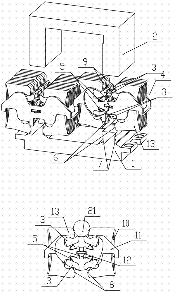
[0034] in the attached Figure 7 with 8 Among them, the circuit breaker body 26 is placed in the cradle 28 of the withdrawable circuit breaker 29, and the circuit breaker body 26 can be withdrawn or inserted in the cradle 28. One or more fixed terminals 1 are installed in the bottom frame 23 of the chassis through screw assemblies 22, the external electrical terminals 24 are connected to the fixed terminals 1, the plug-in clamps 4 are installed on the fixed terminals 1, and the plug-in terminals 2 is fixed on the circuit breaker body 26.

[0035] Each stage of the withdrawable circuit breaker 29 contains several plug-in terminals 2, each of which is electrically connected to the corresponding fixed terminal 1 by plug-in clamps 4 in the plug-in position.

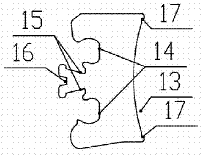
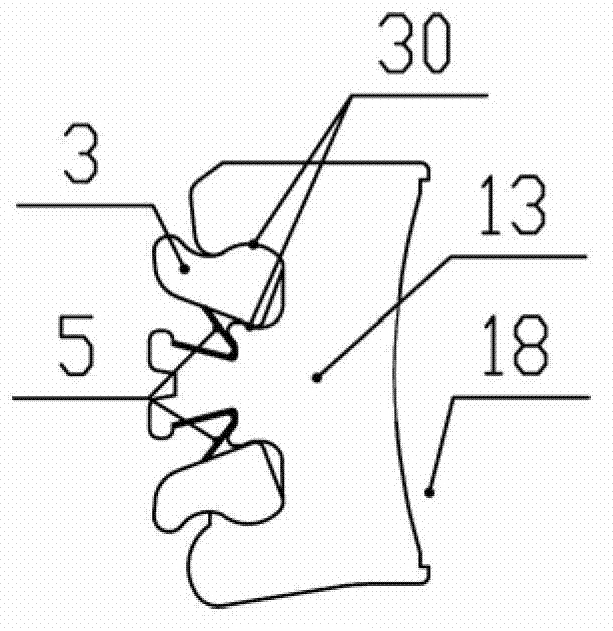
[0036] Such as image 3 As shown, the contact piece 13 is provided with a containing cavity 14, a card slot 16 and a groove 15, as Figure 4As shown, the movable contact 3 is installed in the containing cavity 14, the fre...


PUM


Abstract

The invention provides an electric connection structure of a switch device. The electric connection structure of the switch device is used for a drawout breaker. The electric connection structure comprises at least a fixed type terminal, at least a plug-in type terminal and at least a plug-in type chunk. The plug-in type terminal is inserted in the middle of the plug-in type chunk and is used for connecting with an external electric terminal in an electric mode, wherein the external electric terminal is connected to the fixed type terminal. The plug-in type terminal, the fixed type terminal and the plug-in chunk are in a multiple contact mode when in a working state. The electric connection structure of the switch device has the advantages that electric conduction ability is enhanced, deviation rectifying ability is good, reliable electric connection is guaranteed, product cost is reduced and market competitiveness is increased.

Description

technical field [0001] The invention belongs to the electrical field, in particular to an electrical connection structure of a switchgear, in particular to an electrical connection structure of a withdrawable circuit breaker. It is translatable relative to the fixed chassis between a "connected" position, a "test" position and a "disconnected" position. There is an opening in the front of the chassis for pulling out the circuit breaker body, and an electrical connection structure is provided on the bottom frame opposite to the opening, through which the connection between the circuit breaker body and the bus bar outside the chassis is realized. This structure belongs to electrical field. Background technique [0002] The electrical connection between the body of the withdrawable circuit breaker and the chassis is realized by drawing and inserting the conductive structure. This contact is usually realized by the external terminal, the insertion terminal and the structure tha...

Claims


Application Information

Patent Timeline
IPC IPC(8): H01H71/08
CPCH02B11/04
Inventor 南寅宇文丽霞刘延炎单保卫
Owner BEIJING PEOPLES ELECTRIC PLANT
Learn More