Method of realizing hardware status indication

A technology of hardware status and indication, applied in hardware monitoring and other directions, can solve problems such as troublesome board design, and achieve the effect of reducing device cost and overhead

Inactive Publication Date: 2013-05-08
LANGCHAO ELECTRONIC INFORMATION IND CO LTD
View PDF4 Cites 7 Cited by
  • Summary
  • Abstract
  • Description
  • Claims
  • Application Information

AI Technical Summary

Problems solved by technology

This can cause a lot of trouble for compact and very high-state board designs

Method used


Image

  • Method of realizing hardware status indication
  • Method of realizing hardware status indication

Examples


Embodiment Construction

[0021] A method for realizing hardware status indication of the present invention will be described in detail below in conjunction with the accompanying drawings.

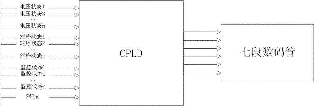
[0022] The invention proposes a method for realizing these state displays based on CPLD and seven-segment digital tubes. This is because the CPLD is used in the hardware system for the sequential logic control of the system. Therefore, on the one hand, this method can greatly reduce the overhead of layout and wiring resources in hardware design, and can also reduce device costs. The method for realizing hardware state indication has a structure as attached figure 1 As shown, it is mainly composed of a CPLD and a seven-segment digital tube. One end of the CPLD is connected to each status indication signal on the main board to receive status information. The CPLD will process each state information accordingly, convert it into the driving signal of the seven-segment digital tube and send it to the seven-segment di...


PUM


Abstract

The invention provides a method of realizing hardware status indication. The structure comprises a complex programmable logic device (CPLD) and a seven-segment nixie tube, wherein one end of the CPLD is connected with status indication signals on a mainboard, the CPLD finishes collecting the induction signals on the mainboard and classify and settle the collected signals, coherent signals are encoded according to priority levels and sequential relationships, and the seven-segment nixie tube is used for receiving correlative coding and display the correlative coding. Compared with the prior art, the method of realizing the hardware status indication reduces overheads of status indication circuits in circuit designs, reduces overheads of layouts and routing resources in hardware designs, and reduces device cost at the same time.

Description

technical field [0001] The invention relates to the technical field of state indication, in particular to a method for realizing hardware state indication by using a seven-segment digital tube. Background technique [0002] In circuit hardware design, we will encounter many states that need to be indicated, such as voltage state, timing state, etc. [0003] In the past, conventional indication methods all used LED indicators. This requires a corresponding LED indicator for each state. With the development of technology, some hardware systems in the computer field are becoming larger and larger. It needs to indicate voltage, timing, and various monitoring states. There are also more and more LED indicators required. The area occupied by the indicator light and the wiring resources will also increase. This can cause a lot of trouble for compact and very high-state board designs. Contents of the invention [0004] The technical task of the present invention is to solve th...

Claims


Application Information

Patent Timeline
Patent Type & Authority Applications(China)
IPC IPC(8): G06F11/32
Inventor 彭勇叶丰华
Owner LANGCHAO ELECTRONIC INFORMATION IND CO LTD
Why Eureka
Try Eureka