Eureka AIR delivers breakthrough ideas for toughest innovation challenges, trusted by R&D personnel around the world.

Horizontal type cyclone combustion biomass burning machine

A cyclone combustion, biomass technology, applied in the direction of combustion method, combustion equipment, solid fuel combustion, etc., can solve the problems of timing shutdown cleaning, fuel can not be fully burned, can not be used, etc., to achieve long service life, ensure combustion effect, The effect of preventing backfire

Active Publication Date: 2013-05-08
胡光
View PDF6 Cites 12 Cited by
  • Summary
  • Abstract
  • Description
  • Claims
  • Application Information

AI Technical Summary

Problems solved by technology

[0002] The traditional biomass pellet burner has a flat-bottomed fixed grate at the bottom, and the combustion uses a blower to force the air from under the grate. This kind of grate needs a certain gap to meet the oxygen supply of the biomass fuel combustion process. However, during the combustion process, biomass fuel will always form coke due to incomplete combustion, so it is necessary to deal with coke continuously to prevent coking and cover the fixed grate completely, otherwise black smoke will appear. Processing will cause the furnace to go out
Therefore, the problem existing in the existing biomass burner is that it is necessary to choose a fuel that will not coke. Even if a fuel that does not coke is selected, a large amount of ash will accumulate on the grate after a long period of operation, resulting in the effective fuel area of ​​the grate. The situation becomes smaller, the fuel cannot be fully burned, and the situation gradually becomes larger, and it is necessary to stop regularly to clean the grate
Cannot be used if coked fuel is selected

Method used


Image

  • Horizontal type cyclone combustion biomass burning machine
  • Horizontal type cyclone combustion biomass burning machine
  • Horizontal type cyclone combustion biomass burning machine

Examples


Embodiment Construction

[0018] The specific implementation manner of the present technology will be further described below in conjunction with the accompanying drawings.

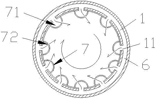
[0019] Such as Figure 1-3 The horizontal cyclone combustion biomass burner shown includes a horizontal cylindrical furnace 1, one end of the furnace is closed, and the closed end 2 has an outlet of a fuel feeding channel 3; a feeding auger is arranged in the fuel feeding channel 4. The fuel feed channel is provided with a tuyere 5 for blowing air toward the outlet of the fuel feed channel; there is an air intake channel 6 in the furnace wall. Both the air inlet passage 6 and the air blast port 5 communicate with the air outlet 9 of the blower. A cyclone tube 7 is arranged on the inner wall of the furnace, and the cyclone tube inner chamber 71 communicates with the air inlet passage 6; an air outlet hole 72 is arranged on the cyclone tube, and the axial direction of the air outlet hole forms an acute angle of 30-60° with the radi...


PUM


Abstract

The invention provides a horizontal type cyclone combustion biomass burning machine, wherein the horizontal type cyclone combustion biomass burning machine enables fuel to burn sufficiently, prevents the fuel from coking and accumulating and has a long service life. The horizontal type cyclone combustion biomass burning machine comprises a horizontal type cylindrical combustion chamber, wherein one end of the combustion chamber is closed, and the closed end is provided with an outlet of a fuel feeding passageway. A feeding auger is arranged inside the fuel feeding passageway, and a blower nozzle which is used for blowing air to the outlet of the fuel feeding passageway is arranged on the fuel feeding passageway. A wind inlet passageway is formed in the wall of the combustion chamber, a cyclone pipe is arranged on the inner wall of the combustion chamber, and an inner cavity of the cyclone pipe is communicated with the wind inlet passageway. Wind outlets are formed in the cyclone pipe, an acute angle is formed between the axial direction of each wind outlet and the radial direction of the cylindrical combustion chamber, and therefore gas which enters the inner cavity of the cyclone pipe from the wind inlet passageway and comes out from the wind outlets is enabled to form vortexes rotating in the same direction in the cylindrical combustion chamber.

Description

technical field [0001] The technology relates to a burner, specifically, a horizontal cyclone burning biomass burner. Background technique [0002] The traditional biomass pellet burner has a flat-bottomed fixed grate at the bottom, and the combustion uses a blower to force the air from under the grate. This kind of grate needs a certain gap to meet the oxygen supplement during the combustion process of biomass fuel. However, during the combustion process, biomass fuel will always form coke due to incomplete combustion, so it is necessary to deal with coke continuously to prevent coking and cover the fixed grate completely, otherwise black smoke will appear. Disposal will cause the furnace to go out. Therefore, the problem existing in the existing biomass burner is that it is necessary to choose a fuel that will not coke. Even if a fuel that does not coke is selected, a large amount of ash will accumulate on the grate after a long period of operation, resulting in the effec...

Claims


Application Information

Patent Timeline
IPC IPC(8): F23B40/00F23L5/00
Inventor 胡光
Owner 胡光
Why Eureka
Eureka Blog
Learn More