
Dental light using LEDs

A LED light source, dental technology, applied in the direction of dentistry, dental drilling, application, etc., can solve the problem of color matching of soft tissue pathology that is difficult for dentists to check

Inactive Publication Date: 2013-05-01
A DEC INC
View PDF6 Cites 8 Cited by
  • Summary
  • Abstract
  • Description
  • Claims
  • Application Information

AI Technical Summary

Problems solved by technology

The color rendering index (CRI) of LEDs is generally smaller than that of conventional light sources, making it difficult for dentists to examine soft tissue pathology and utilize LED lights for color matching

Method used


Image

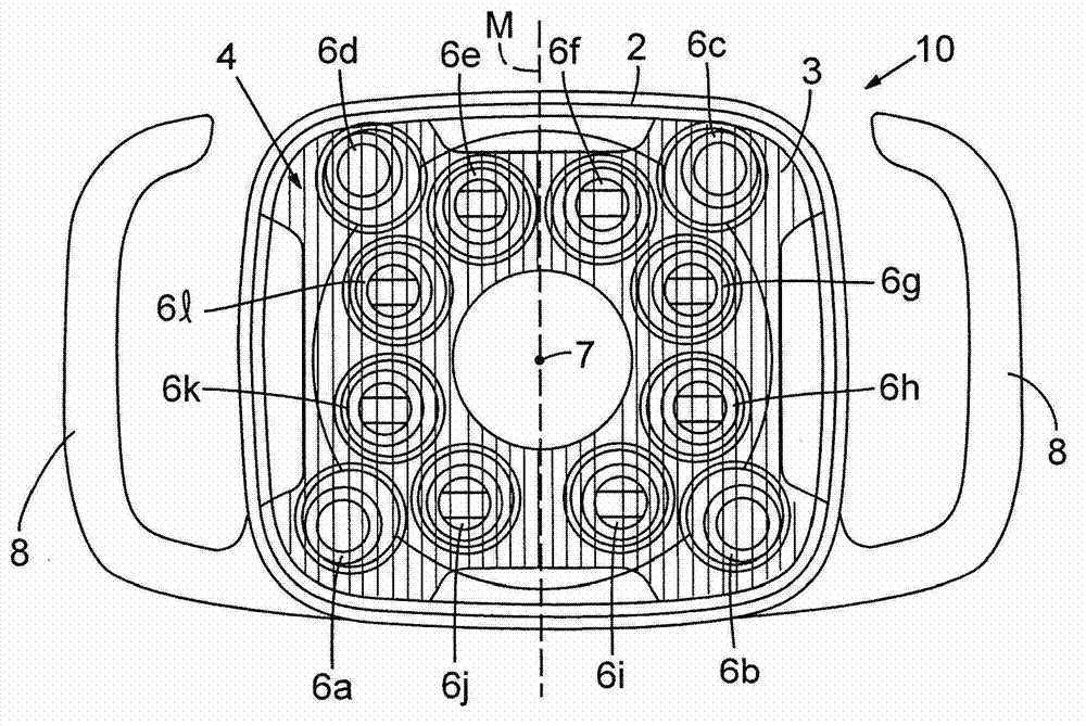
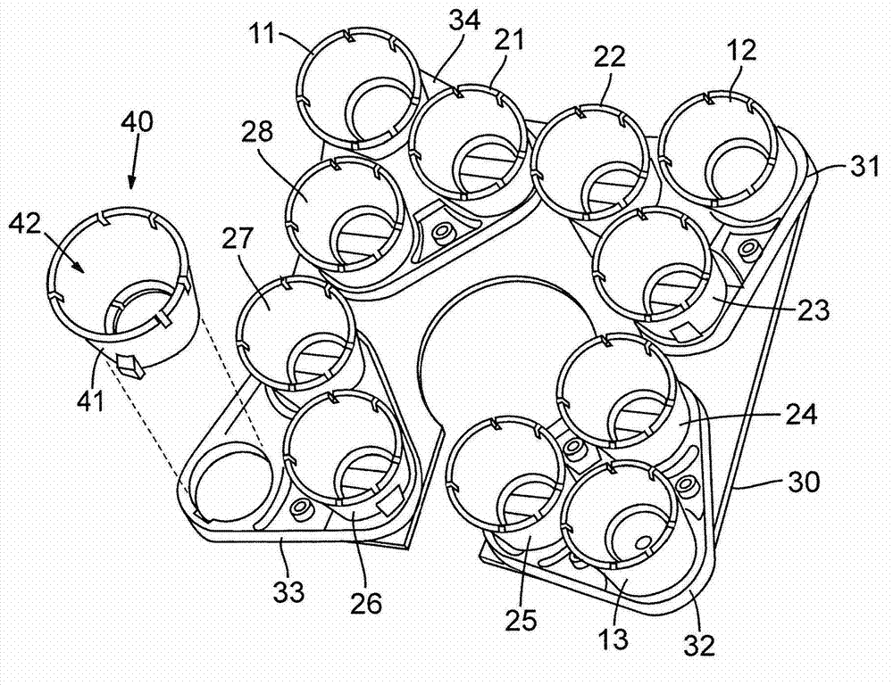
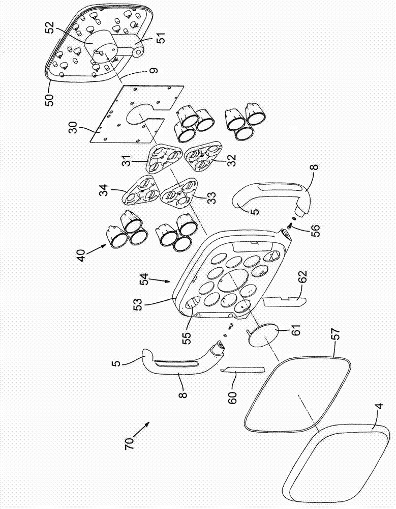
  • Dental light using LEDs
  • Dental light using LEDs
  • Dental light using LEDs

Examples


Embodiment approach

[0135] Other implementations are included in the technical solutions described below:

[0136] 1. A dental light comprising: at least one light emitting diode (LED) light source configured to generate a light beam along a path; and at least one collimating lens system positioned to receive the light beam and configured to pass through the controlled Diffuse mixes light within the beam to improve color uniformity of the beam.

[0137] 2. The dental light of preceding claim 1, wherein said at least one collimating lens system includes a diffuser configured to produce said controlled diffusion.

[0138] 3. The dental light according to any one of the preceding technical solutions 1-2, wherein mixing the light in the light beam by controlled diffusion is such that a uniform light beam is produced at a predetermined illumination plane.

[0139] 4. The dental light according to any one of the preceding technical solutions 1-3, wherein the diffuser is a transparent optical element w...


PUM


Abstract

A dental light comprises at least one light emitting diode light source configured to produce a light beam and at least one collimating lens system situated to receive the light beam. The collimating lens system is configured to collect and collimate the light beam. The collimating lens system can additionally modify the beam through controlled diffusion or shape the beam using an aperture.

Description

technical field [0001] This application relates to LED lights, and more particularly to LED lights used in dentistry. Background technique [0002] In the dental industry, dental lights - also known as dental operating lights or dental light fixtures - are used to illuminate a patient's mouth (oral cavity) during dental procedures. For example, dental lights aid in patient examination and diagnosis, tooth reduction and preparation, shade matching and restoration. [0003] Current dental lights mainly use incandescent lamps or quartz halogen lamps as light sources. These light sources are also often used with reflectors such as mirrors or other reflective surfaces. Light-emitting diode (LED) light sources offer several advantages over these sources, including long life, low power consumption, and greatly reduced radiant heat. [0004] However, there are some difficulties in applying LED light sources to dental lights. For example, in various dental applications, the quali...

Claims


Application Information

Patent Timeline
Patent Type & Authority Applications(China)
IPC IPC(8): F21S8/00F21V5/04F21V5/08H05B37/02F21W131/202F21Y101/02
CPCF21V15/011F21Y2105/001F21V21/26F21W2131/202F21V5/002F21Y2101/02F21V29/004F21V5/007F21V11/08F21V29/507F21Y2115/10F21V21/30F21Y2105/10F21V5/04F21V29/70F21V23/005F21Y2101/00F21K9/62A61B1/0684A61B1/24A61C1/088F21V21/28F21V31/005F21V33/0068G02B27/30
Inventor C·C·斯通中川隆晶E·布伯R·J·朗斯代尔P·W·贝利R·M·威廉姆斯J·V·多梅伦J·阿尔瓦雷斯J·E·迈尔斯
Owner A DEC INC
Learn More