
Laser device wide-temperature circuit

A laser and circuit technology, applied in the field of laser applications, can solve the problems of damaged laser performance, large circuit parameter drift, large volume, etc., and achieve the effects of easy processing and assembly, strong portability, and high integration

Inactive Publication Date: 2013-04-24
QINGDAO LASENCE
View PDF8 Cites 3 Cited by
  • Summary
  • Abstract
  • Description
  • Claims
  • Application Information

AI Technical Summary

Problems solved by technology

[0004] At present, the laser drive circuits on the market work normally at room temperature. The laser power control circuit generally drives the triode directly through the operational amplifier as a comparator. The comparator output has two states Vmax and Vmin. By changing the duty cycle To achieve power stability control, the upper limit current is achieved by setting the base resistance value of the triode to reach the target current value. Such current limitation is realized by the magnification β value of the triode, and there is no temperature compensation device, and the current limit value changes with temperature. At low temperature or high temperature, the parameters of the entire circuit will drift greatly, and there are many shortcomings: 1. The set power of the laser drifts, which makes the laser overwork and damages the performance of the laser
2. The upper limit current changes. At low temperature, the upper limit current will become very low, and it is almost impossible to drive the laser normally. At high temperature, the current will be too high, which will damage the performance of the laser.
3. The large volume is not conducive to the application in important fields such as military affairs

Method used


Image

  • Laser device wide-temperature circuit
  • Laser device wide-temperature circuit
  • Laser device wide-temperature circuit

Examples


Embodiment 1

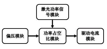
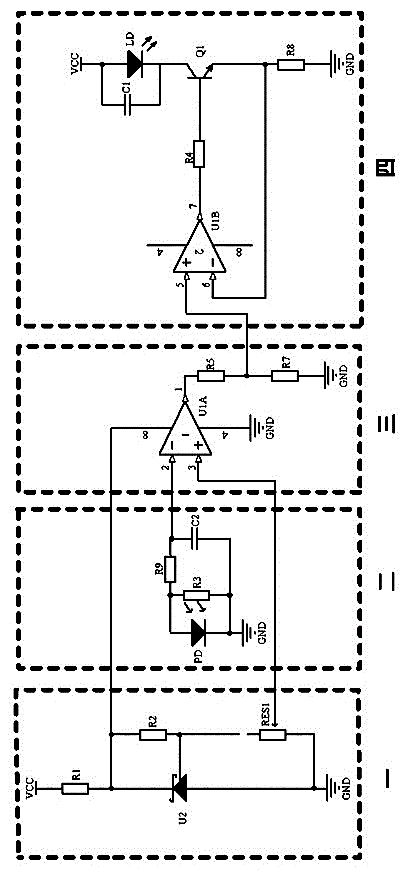
[0021] One: Bias module.

[0022] Two: laser power signal module.

[0023] Three: power duty cycle module.

[0024] Four: drive current module.

[0025] The laser wide temperature circuit of the present invention includes a bias voltage module, a laser power signal module, a power duty ratio control module, and a driving current module, wherein the bias voltage module and the laser power signal module are all connected to the power duty ratio module, and the power duty ratio The module and the drive circuit module are connected. The bias voltage module includes a reference voltage regulator chip and a potentiometer. The reference voltage regulator chip outputs a reference voltage, and then uses the potentiometer to divide the voltage to output a suitable voltage range. The voltage of the middle tap of the potentiometer is used as the setting of the power duty cycle module. value, the power is continuously adjustable within the set range. The laser power signal module inclu...

Embodiment 2

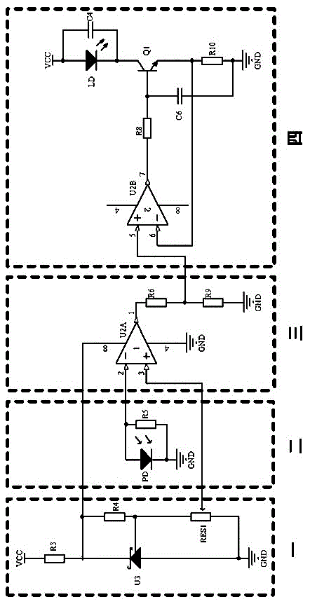
[0036] One: Bias module.

[0037] Two: laser power signal module.

[0038] Three: power duty cycle module.

[0039] Four: drive current module.

[0040] The difference between this embodiment and Embodiment 1 is that the laser power signal module of this embodiment omits the low-pass filter circuit, and also realizes the high-speed import of the power signal to the power duty cycle module for comparison, and quickly adjusts the optical power.

[0041]The laser power signal module of this embodiment: According to the characteristic that the photodiode (PD) generates a corresponding amount of optical feedback current for different power laser light intensity signals, we add an optical feedback component containing a photodiode (PD) to the light output optical path of the laser (APD). The current-voltage conversion is performed on the feedback current, and the laser power signal is imported to the power duty cycle module at high speed, providing an instant power signal ...


PUM


Abstract

The invention relates to the field of laser application, in particular to the field of the laser application with more strict temperature change requirement. The invention provides a laser device wide-temperature circuit which achieves that the size is small, and the upper limit of current is set with high accuracy, dynamic regulation is achieved with drive current, laser power is controlled with high accuracy, and response to the temperature change is minimal. The laser device wide-temperature circuit comprises a bias module, a laser power signal module, a power duty radio module, and a drive current module, wherein the bias module and the laser power signal module are both connected with the power duty radio module, and the power duty radio module is connected with the drive current module. According to the laser device wide-temperature circuit, a laser drive circuit with small size, wide temperature and low temperature drift is achieved. The laser device wide-temperature circuit is high in integration level, strong in transportability, easy to process and assemble, and economical in cost. The laser device wide-temperature circuit can be used in the fields of military, measurement and other fields with more strict requirements on size and which need a wider range of temperature.

Description

[0001] technical field [0002] The invention relates to the field of laser application, especially the field of laser application with relatively strict temperature change requirements. Background technique [0003] With the continuous development of science and technology, the application scope of laser is also expanding rapidly, such as: medical equipment, construction measurement, instruction, military, aerospace and so on. Applications in these areas require stable power output of the laser, and stricter requirements on durability. This puts forward two requirements for the drive circuit: 1. The laser setting power value should be stable and not change with temperature. 2. The drive circuit must have a stable upper limit current to prevent the laser from being burned by automatic control to increase the drive current when the laser output power is not enough. [0004] At present, the laser drive circuits on the market work normally at room temperature. The laser power...

Claims


Application Information

Patent Timeline
Patent Type & Authority Applications(China)
IPC IPC(8): H01S5/042H01S5/06
Inventor 邱港陆之成马世建
Owner QINGDAO LASENCE
Learn More