Positive-intrinsic-negative (PIN) diode array structure and manufacturing method thereof
A PIN diode and array structure technology, applied in the field of semiconductor integrated circuits, can solve the problems of high cost and large volume, achieve low cost, improve reverse isolation, and reduce forward insertion loss
- Summary
- Abstract
- Description
- Claims
- Application Information
AI Technical Summary
Problems solved by technology
Method used
Image
Examples
Embodiment Construction
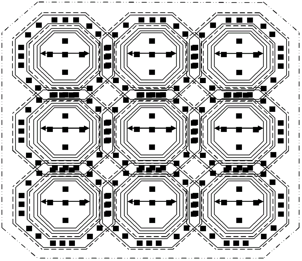
[0026] The PIN diode array structure of the present invention is composed of a plurality of PIN diode single tubes connected in parallel, and each PIN diode single tube includes a substrate 1, an N-type cathode 2, an intrinsic semiconductor 3, a P-type anode 7, an isolation region 4, an N-type outer base cathode 5. In order to minimize the parasitic capacitance, the array formed in parallel is preferably or close to a square, such as figure 2 As shown in the top view of the array structure, the array structure has 9 PIN diode single tubes forming a 3×3 square array, and adjacent PIN diode single tubes share the N-type outer base region cathode 5 .
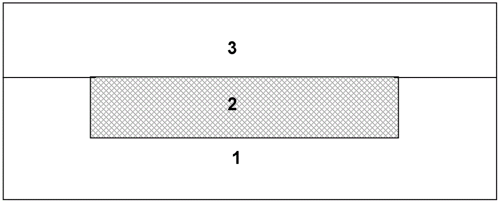
[0027] A disc-shaped N-type cathode 2 is formed above the substrate 1, an intrinsic semiconductor 3 with a thickness of 1.2 μm to 3 μm is grown above the middle part of the disc-shaped N-type cathode 2, and the peripheral part of the disc-shaped N-type cathode 2 is An annular N-type extrinsic base cathode 5 coaxial with the disk-...
PUM
 Abstract
Description
Claims
Application Information
 - R&D
- Intellectual Property
- Life Sciences
- Materials
- Tech Scout
- Unparalleled Data Quality
- Higher Quality Content
- 60% Fewer Hallucinations
Browse by: Latest US Patents, China's latest patents, Technical Efficacy Thesaurus, Application Domain, Technology Topic, Popular Technical Reports.
© 2025 PatSnap. All rights reserved.Legal|Privacy policy|Modern Slavery Act Transparency Statement|Sitemap|About US| Contact US: help@patsnap.com


