Piston type pneumatic circulating gas pump

A circulating air pump, piston-type technology, applied in the field of piston-type pneumatic circulating air pump, can solve the problems of power consumption, waste of fuel safety, stack pressure fluctuations, etc., and achieve the effects of no hydrogen loss, improved comfort, and no power consumption

Active Publication Date: 2013-04-24
上海新源动力有限公司
View PDF7 Cites 8 Cited by
  • Summary
  • Abstract
  • Description
  • Claims
  • Application Information

AI Technical Summary

Problems solved by technology

For fuel cell vehicles, the discharge of hydrogen from the stack is a waste of fuel (the lost H 2 Fuel up to 5%) has potential safety hazards, and will cause pressure fluctuations inside the stack, which will affect the service life of the membrane e

Method used


Image

  • Piston type pneumatic circulating gas pump
  • Piston type pneumatic circulating gas pump
  • Piston type pneumatic circulating gas pump

Examples


Embodiment 1

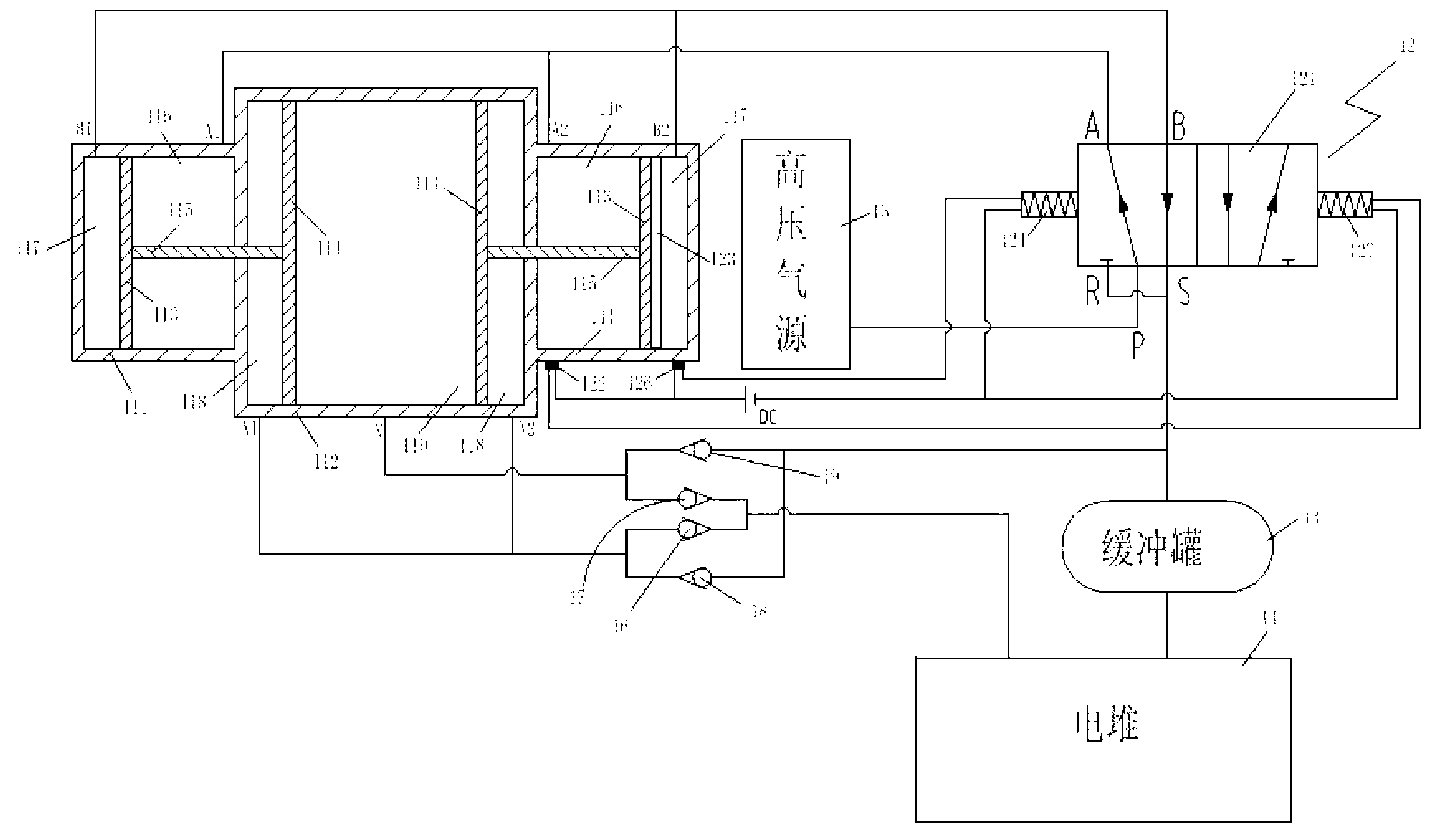
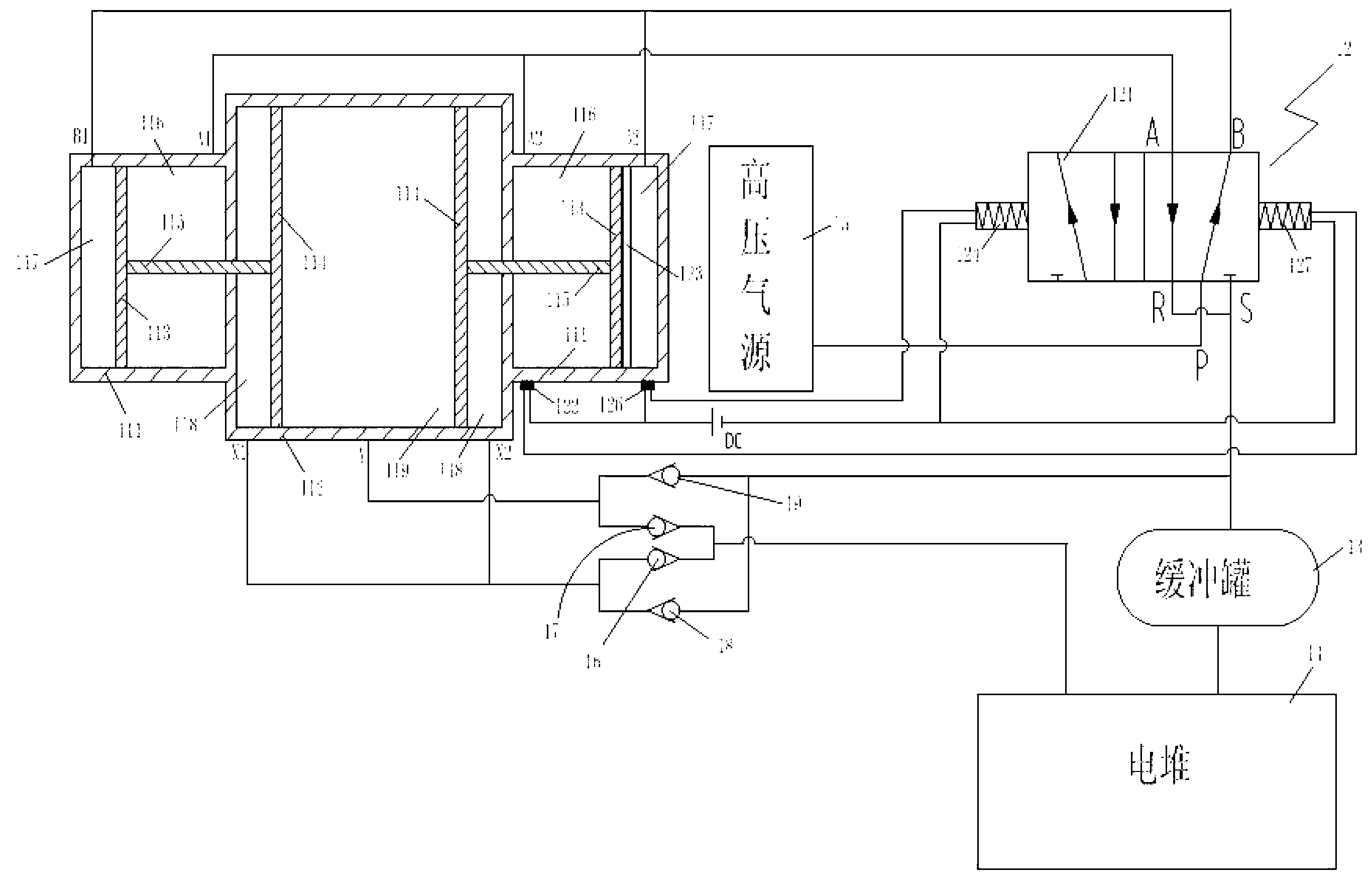
[0029] see figure 1 , figure 2 A piston-type pneumatic circulating air pump shown includes a circulating air pump pump body, a gas reversing mechanism 12, a buffer tank 13 and an electric stack 14,

[0030] The pump body of the circulating air pump includes two small cylinders 111 and a large cylinder 112 arranged horizontally on the same axis. The two small cylinders 111 are symmetrically arranged on both sides of the large cylinder 112. Each small cylinder 111 is respectively equipped with a small piston 113. 1. Two large pistons 114 are arranged in the large cylinder 112, and the large piston 114 and the small piston 113 are connected by corresponding piston rods 115; A first chamber 116 is formed between the partition wall and the small piston, and the other is a second chamber 117; the large piston 114 divides the large cylinder 112 into two chambers, wherein the partition wall of the large and small cylinders and the large piston A third cavity 118 is formed, and the ...

Embodiment 2

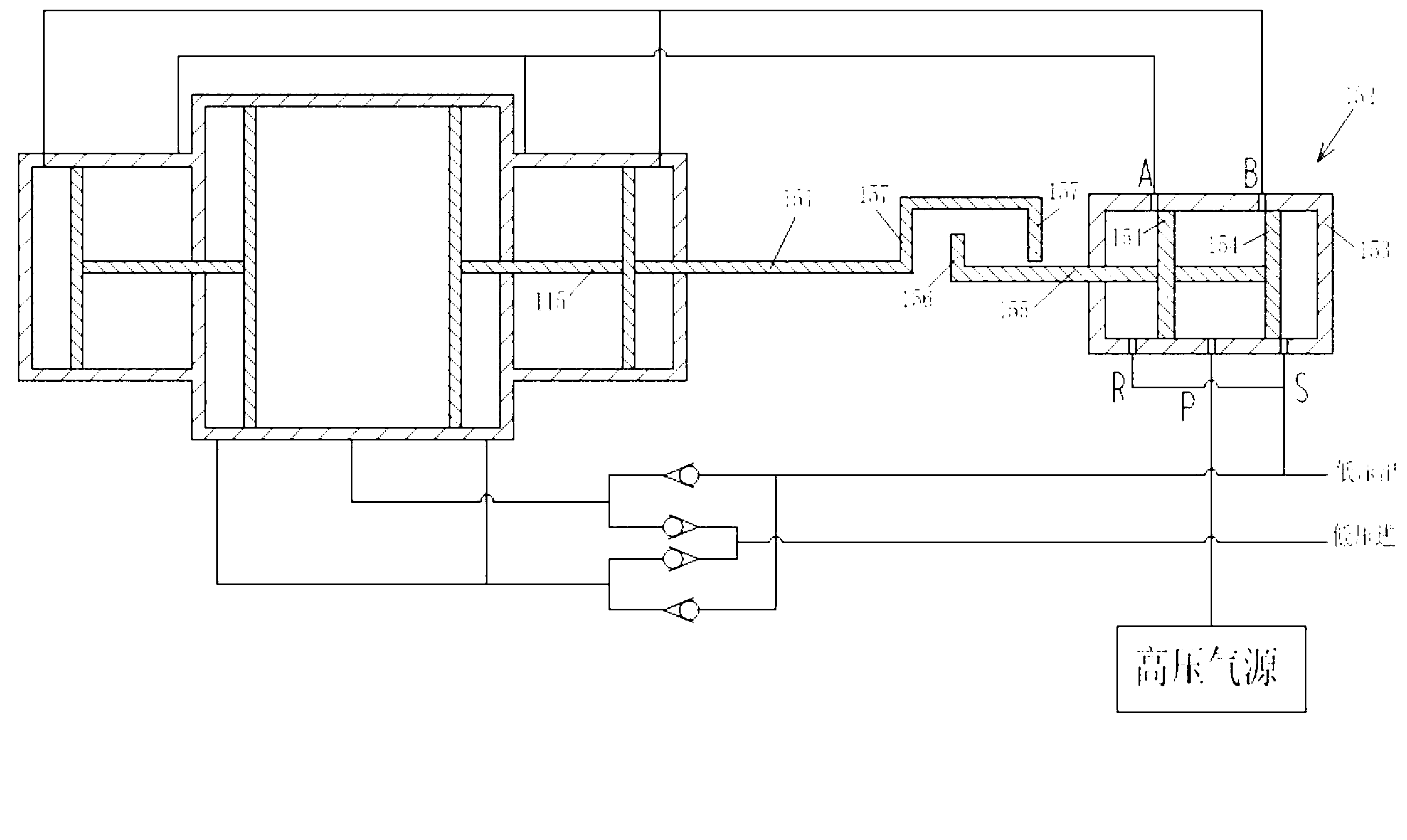
[0043] see you again image 3 As shown, the difference between this embodiment and Embodiment 1 is that the switching mechanism includes a shifting lever 151, the two-position five-way reversing valve is a mechanical two-position five-way reversing valve 152, and the inner end of the shifting rod 151 is connected to the The piston rod 115 is connected and fixed, and the outer end of the driving rod 151 has a concave structure; the mechanical 2-position 5-way reversing valve 152 includes a valve body 153, two spools 154 and a driven rod 155, and the spool 154 is set on the valve In the body 153, the inner end of the driven rod 155 is connected to the spool 154, and the outer end of the driven rod 155 is provided with a protrusion 156, and the protrusion 156 extends into the concave outer end of the driving rod 151, and the piston rod 115, The axes of the driving rod 151 and the driven rod 155 coincide;

[0044] Both sides of the concave outer end are respectively provided with...


PUM


Abstract

The invention discloses a piston type pneumatic circulating gas pump which comprises a circulating gas pump body, a gas reversing mechanism, a buffering tank and an electric pile. The circulating gas pump body comprises a big cylinder and small cylinders, a big piston is arranged in the big cylinder and divides the big cylinder into two cavities, a small piston is arranged in each small cylinder and divides the corresponding small cylinder into two cavities, the gas reversing mechanism comprises a two-position five-way reversing valve and a replacing mechanism with one end connected with the circulating gas pump body and the other end connected with the two-position five-way reversing valve, a gas outlet of the electric pile is communicated with a third cavity in the big cylinder through a first check valve and further communicated with a fourth cavity in the big cylinder through a second check valve, the third cavity is communicated with a gas inlet of the buffering tank through a third check valve, and the fourth cavity is communicated with the gas inlet of the buffering tank through a fourth check valve. Circulatory flowing of hydrogen in the electric pile is realized through expansion work released during decompression of compressed hydrogen.

Description

technical field [0001] The present invention relates to a piston type air pump, more specifically, relates to a piston type pneumatic circulating air pump. Background technique [0002] A proton exchange membrane fuel engine system is a power generating device that directly converts the chemical energy in a fuel (usually hydrogen or methanol) into electrical energy through an electrochemical reaction. Unlike conventional power plants, it does not need to convert the chemical energy in the fuel first into heat and then into electricity. Therefore, compared with traditional power generation devices, fuel cells have the significant advantages of high energy conversion efficiency and less pollutant emissions. [0003] In order to ensure the continuous and normal operation of the proton conduction membrane fuel cell system (referred to as PEMFCS), it is necessary to discharge the liquid water and impurity gas condensed on the anode interface of the stack in time. Existing PEMFC...

Claims


Application Information

Patent Timeline
IPC IPC(8): F04B35/02H01M8/04H01M8/04089
CPCY02E60/50
Inventor 罗涛陈华胡军
Owner 上海新源动力有限公司
Why Eureka
Try Eureka