
Device for measuring downhole flow while drilling and monitoring early overflow

A technology of flow measurement device and fluid guiding device, which is applied in the direction of measurement, earthwork drilling, wellbore/well components, etc., can solve problems such as lagging and distortion of monitoring results, achieve high monitoring accuracy, prevent lost circulation, and benefit The effect of prevention and control

Inactive Publication Date: 2013-04-24
SOUTHWEST PETROLEUM UNIV
View PDF7 Cites 35 Cited by
  • Summary
  • Abstract
  • Description
  • Claims
  • Application Information

AI Technical Summary

Problems solved by technology

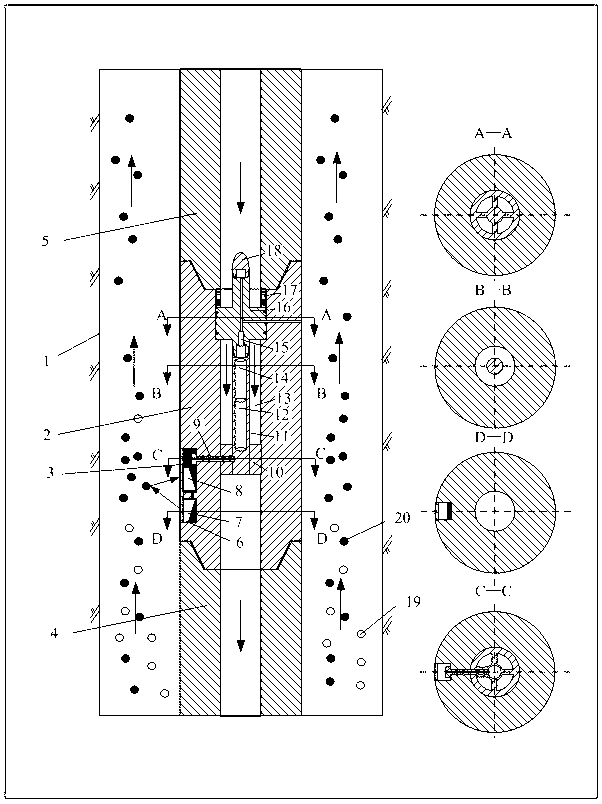
[0005] The purpose of the present invention is to overcome the problems of distortion and hysteresis of the monitoring results of the conventional monitoring method, make up for the shortcomings of the conventional monitoring method, and provide a device and method for monitoring the early overflow of the downhole annular flow rate measurement while drilling. The device can measure the flow rate, pressure, temperature and other parameters of the annulus near the drill bit downhole while drilling. The device can be connected with MWD (Measurement While Drilling) to upload real-time downhole measured data, and comprehensively analyze and process the downhole real-time uploaded data and ground-related data. , can judge downhole overflow in real time, so as to achieve the purpose of monitoring early overflow and effectively improve the safety of drilling well control

Method used


Image

  • Device for measuring downhole flow while drilling and monitoring early overflow
  • Device for measuring downhole flow while drilling and monitoring early overflow
  • Device for measuring downhole flow while drilling and monitoring early overflow

Examples


Embodiment Construction

[0015] The implementation of the present invention will be described below in conjunction with the accompanying drawings.

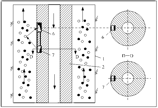
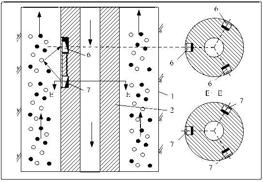
[0016] exist figure 1Among them, there are slots (6) on the outer wall of the drill collar sub (2) of the downhole flow measurement device while drilling, and the slots (6) are at two different cross-sectional positions in the same generatrix direction of the drill collar sub (2) , an ultrasonic transmitting sensor (7) and a receiving sensor (8) are installed in the card slot (6), the ultrasonic sensor includes an ultrasonic transmitting sensor (7) and an ultrasonic receiving sensor (8), and the receiving and transmitting sensor faces at an inclination angle of 45° According to the direction of liquid flow in the annular space of the wellbore, a small hole for pressure transmission is opened on the drill collar nipple (2); the probe pipe (2), Annulus fluid guiding device (16), MWD joint (18) and elastic compression gasket (17), the drilling fluid circula...


PUM


Abstract

Disclosed is a downhole flow measuring while drilling device capable of measuring downhole annular flow, annular pressure and annular temperature and monitoring early overflow while drilling. The measuring device measures downhole annular flow and flow change through an ultrasonic wave sensor mounted at a short section of a drill collar and measures annular pressure and annular temperature through a pressure and temperature sensor mounted inside an annular fluid guiding device, a power source and a circuit board are mounted inside an exploring pipe, physical signals, such as annular flow, pressure and temperature, are converted into electric signals through the sensors, the measuring device records, stores and uploads data through the circuit board, and the measuring device is connected with a MWD (measurement while drilling) through an MWD joint to timely upload actually-measured data to the ground. The device is simple in structure, low in manufacturing cost and long in service life, and working conditions such as downhole overflow can be judged in real time by comprehensively analyzing and processing timely-uploaded downhole data and related data on the ground to achieve the objective of early overflow monitoring, so that safety of well control of well drilling is effectively improved.

Description

technical field [0001] The invention relates to a device and a method for measuring and monitoring early overflow in an annular space while drilling, which are used for monitoring early overflow while drilling oil and gas wells. By measuring the downhole annular flow rate, pressure, temperature and wellhead inlet flow parameters while drilling, the change of the downhole annular return flow rate is monitored, so as to achieve the purpose of monitoring early overflow. Background technique [0002] As the exploration and development of my country's oil and gas resources continue to deepen, it has developed from conventional oil reservoirs to hidden oil reservoirs and complex oil reservoirs, from shallow to deep, and from east to west and ocean. The drilling environment has become increasingly harsh and the difficulty of drilling has been increasing Large, complex and harsh working conditions have brought new wellbore pressure control problems, especially for high-pressure gas w...

Claims


Application Information

Patent Timeline
Patent Type & Authority Applications(China)
IPC IPC(8): E21B47/10E21B47/18
Inventor 陈平马天寿黄万志胡泽王旭东任超
Owner SOUTHWEST PETROLEUM UNIV
Learn More