Non-power-outage operated bypass connection device used between two European-style ring main units

A connection device, European-style ring technology, applied in substation/switch layout details, cable terminals, electrical components, etc., can solve the difficulty of connecting the bypass connection device with the European-style ring network cabinet Inconvenient problems such as the connection of road connection devices and the inconvenience of uninterrupted maintenance operations, etc., to achieve the effect of facilitating construction and uninterrupted maintenance operations, facilitating uninterrupted maintenance operations, and improving the reliability of line power supply

Inactive Publication Date: 2013-04-10
SHANGHAI MUNICIPAL ELECTRIC POWER CO +1
View PDF3 Cites 6 Cited by
  • Summary
  • Abstract
  • Description
  • Claims
  • Application Information

AI Technical Summary

Problems solved by technology

[0004] At present, the cable bushings in the European-style ring network cabinet mostly use fully insulated, fully enclosed, and fully sealed cable terminals, which cannot be separated from the cables connected to them.
[0005] When laying the bypass connection device, due to the small space of the inlet hole of the European-style ring network cabinet, and the large volume of the cable terminal enclosed with the bypass connection device, it is impossible to enter the European-style ring network smoothly through the wire inlet hole. cabinet, which makes it more difficult to connect the bypass connection device to the European-style ring network cabinet. Often, the effective connection between the ring network cabinet and the bypass connection device can not be implemented to expand the scope of work, which brings inconvenience to the maintenance operation without power failure
[0006] At the same time, the grounding of the bypass connection device is mainly realized through the grounding wire that is installed on the metal shielding shell of the cable terminal and connected to the ground. , Convenient construction, and such a grounding method requires an additional grounding wire when laying the bypass connection device, which increases the construction time and difficulty, and brings inconvenience to the maintenance operation without power failure

Method used


Image

  • Non-power-outage operated bypass connection device used between two European-style ring main units
  • Non-power-outage operated bypass connection device used between two European-style ring main units

Examples


Embodiment Construction

[0017] The present invention will be further described below in conjunction with the accompanying drawings.

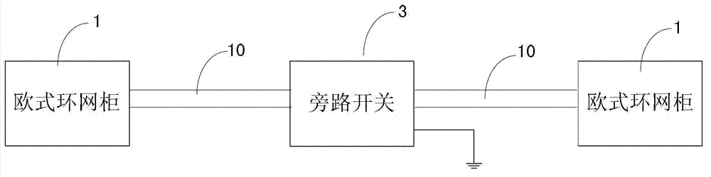
[0018] see figure 1 , the figure shows the bypass connection device of the present invention for non-stop operation between two European-style ring network cabinets, the bypass connection device is set between two European-style ring network cabinets 1, including two flexible cable connection devices 10 One end of the two flexible cable connection devices 10 is connected to the corresponding European-style ring network cabinet 1 , and the other end is connected to the bypass switch 3 .

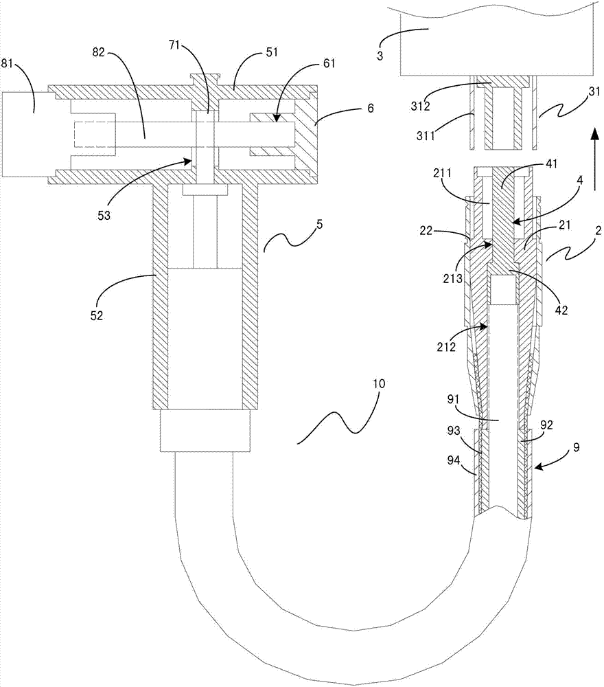
[0019] see figure 2 , the flexible cable connection device is shown in the figure, the flexible cable connection device 10 includes a cable terminal, a flexible cable 9 and a plug-in quick connector 2, and the flexible cable 9 includes a sheath 94, a tinned copper wire shielding layer 93 from the outside to the inside , an inner sheath 92 and a tinned copper conductor 91, the cable ...


PUM


Abstract

The invention discloses a non-power-outage operated bypass connection device used between two European-style ring main units. The non-power-outage operated bypass connection device used between the two European-style ring main units comprises two lines of flexible cables connection devices led out from the two European style ring main units and a by-pass switch arranged between the two lines of flexible cable connection devices. Each of the flexible cables connection devices comprises a cable terminal, a flexible cable and a plug type quick connector. The cable terminal is composed of a detachable T casing pipe and a cable wiring terminal. A cable with the cable wiring terminal is led in from a line inlet arranged on each of the European-style ring main units and is inserted from a lower end mouth of a vertical pipe part of the T casing pipe, thus connection between the cable terminal and a cable sleeve is greatly benefited. According to the non-power-outage operated bypass connection device used between the two European-style ring main units, the touch down point is changed from the cable terminal portion to the by-pass switch portion by using the characteristic of shielded lines all-line connecting of flexible cables, and thus ground lead erecting is not needed. The flexible cables connection devices are simple in structure and convenient to use, reduce operation scope, facilitate not power-outage examine and repair operation and improve line power supply reliability.

Description

technical field [0001] The invention relates to a bypass connection device used for non-power-off operation between two European-style ring network cabinets. Background technique [0002] When the underground cable between the two European-style ring network cabinets needs to be repaired abnormally, after laying the bypass connection device on the ground and taking safety protection measures, the bypass connection device replaces the underground cable to supply power to the ring network cabinet, so as to achieve no power failure (less power failure) The purpose of maintenance. [0003] The bypass connection device is mainly composed of a bypass switch, a cable terminal connected to the cable sleeve of the European-style ring network cabinet at one end, and a flexible cable connected to the bypass switch at the other end. [0004] At present, the cable bushings in the European-style ring network cabinet mostly use fully insulated, fully enclosed, and fully sealed cable termi...

Claims


Application Information

Patent Timeline
Patent Type & Authority Applications(China)
IPC IPC(8): H02B1/00H02G15/02
Inventor 姚建歆张杰朱星昶朱炯王剑顾临峰俞汝川
Owner SHANGHAI MUNICIPAL ELECTRIC POWER CO
Why Eureka
Try Eureka