
Light-emitting element driving circuit, pixel circuit, display panel, and display

A technology for light-emitting elements and driving circuits, which is applied in the fields of display panels and displays, driving circuits for light-emitting elements, and pixel circuits, can solve problems such as affecting the brightness uniformity of organic light-emitting diode displays, and achieve the effect of improving the brightness uniformity.

Inactive Publication Date: 2013-04-10
WINTEK CORP
View PDF6 Cites 43 Cited by
  • Summary
  • Abstract
  • Description
  • Claims
  • Application Information

AI Technical Summary

Problems solved by technology

As a result, the brightness uniformity of the organic light emitting diode display will be affected

Method used


Image

  • Light-emitting element driving circuit, pixel circuit, display panel, and display
  • Light-emitting element driving circuit, pixel circuit, display panel, and display
  • Light-emitting element driving circuit, pixel circuit, display panel, and display

Examples


Embodiment Construction

[0073] Reference will now be made in detail to the exemplary embodiments of the present invention, examples of which are illustrated in the accompanying drawings. In addition, wherever possible, elements / members using the same reference numerals in the drawings and embodiments represent the same or similar parts.

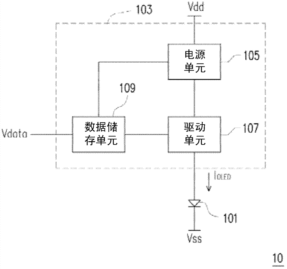
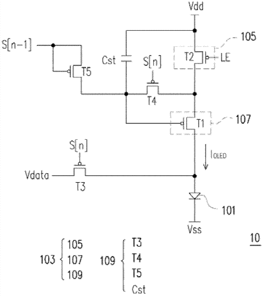
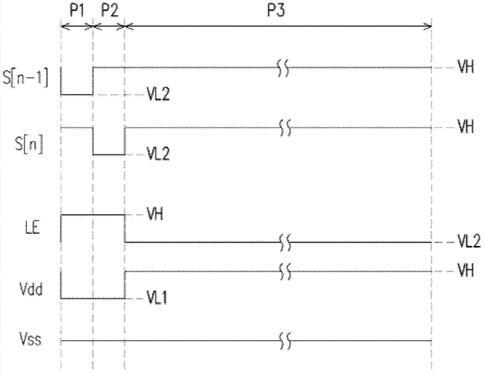
[0074] figure 1 Illustrated as a schematic diagram of an organic light emitting diode pixel circuit (OLED pixel circuit) according to an exemplary embodiment of the present invention, and figure 2 shown as figure 1 Implementation circuit diagram of the OLED pixel circuit. Please merge reference figure 1 and figure 2 , the OLED pixel circuit 10 of this exemplary embodiment includes a light-emitting component (light-emitting component, such as: organic light-emitting diode (OLED) 101, but not limited thereto) and a light-emitting component driving circuit (light-emitting component driving circuit) 103. Wherein, the light emitting device driving circuit 103 inc...


PUM


Abstract

The invention provides a light-emitting element driving circuit, a pixel circuit, a display panel, and a display. When the frame of the driving circuit (5T1C) is cooperated with a proper operating waveform, the current cross an organic light emitting diode cannot change along the power supply voltage (Vdd) under the influences of current, resistance, and voltage drops, and cannot change along the threshold voltage shift (Vth shift) for driving the thin film transistor of the organic light emitting diode. Therefore, the brightness uniformity of the organic light emitting diode display using the same can be greatly improved.

Description

technical field [0001] The present invention relates to a plane display technology, and in particular to a light-emitting element driving circuit, a pixel circuit, a display panel and a display. Background technique [0002] Due to the rapid progress of the multimedia society, the technologies of semiconductor devices and display devices have also undergone rapid progress. As far as the display is concerned, since the active matrix organic light emitting diode (Active Matrix Organic Light Emitting Diode, AMOLED) display has no viewing angle limitation, low manufacturing cost, high response speed (about a hundred times higher than that of liquid crystal), power saving, self-illumination, It can be used for DC drive of portable machines, has a wide operating temperature range, is light in weight, and can be miniaturized and thinned along with hardware devices to meet the characteristic requirements of displays in the multimedia era. Therefore, the active matrix organic light ...

Claims


Application Information

Patent Timeline
Patent Type & Authority Applications(China)
IPC IPC(8): G09G3/32H05B37/02G09G3/3258
Inventor 王文俊韩西容廖文堆黄志鸿王宗裕
Owner WINTEK CORP
Learn More