
Double charge-coupled-device (CCD) mirror image overlap adjustment and single-exposure coaxial digital holographic record device

A technology of adjusting device and mirror, applied in the field of digital holography, can solve the problems of difficulty in manufacturing phase-shifting devices, poor versatility, high price, etc.

Inactive Publication Date: 2013-04-10
ZHEJIANG UNIVERSITY OF SCIENCE AND TECHNOLOGY
View PDF5 Cites 20 Cited by
  • Summary
  • Abstract
  • Description
  • Claims
  • Application Information

AI Technical Summary

Problems solved by technology

The disadvantage of this technology is that the manufacture of the phase shifting device is difficult, expensive, and poor in versatility. In addition, it has very strict requirements on the adjustment of the optical path. It is necessary to make each pixel of the phase shifting device be imaged with the imaging lens The pixels of the CCD are aligned one by one, and at the same time, the diffraction effect of the reference light through the phase shift device to avoid modulation and the optical distortion introduced by the imaging lens are not considered.
The disadvantage of this technology is that it needs to use a special CCD, which brings difficulties to the experiment, and only two phase-shift holograms can be obtained. The conditions for solving the phase-shift equation are not sufficient, so only objects with uniform light intensity distribution can be recorded.

Method used


Image

  • Double charge-coupled-device (CCD) mirror image overlap adjustment and single-exposure coaxial digital holographic record device
  • Double charge-coupled-device (CCD) mirror image overlap adjustment and single-exposure coaxial digital holographic record device
  • Double charge-coupled-device (CCD) mirror image overlap adjustment and single-exposure coaxial digital holographic record device

Examples


Embodiment Construction

[0028] The present invention will be described in further detail below in conjunction with the accompanying drawings.

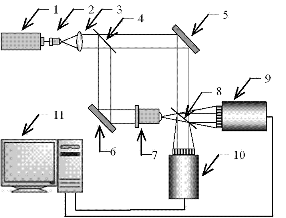
[0029] see figure 1 Shown is the schematic diagram of the adjustment device of two CCD image overlapping positions in the device of the present invention, and the adjustment device includes a laser light source 1, a beam expander collimation system 2-3, a beam splitter 4, a plane reflector 5, a plane reflector 6, Beam expander lens 7, beam splitter 8, first CCD camera 9, second CCD camera 10 (fixed on the three-dimensional adjustment platform), computer 11.

[0030] Instructions for adjusting the mirror overlap of the two CCDs relative to the beam splitter 8:

[0031] The linearly polarized coherent light emitted by the laser light source 1 is expanded and collimated into planar light by the beam expander and collimator system 2-3, and is divided into two beams of planar light by the beam splitter 4, one of which is reflected by the plane reflector 5, and th...


PUM


Abstract

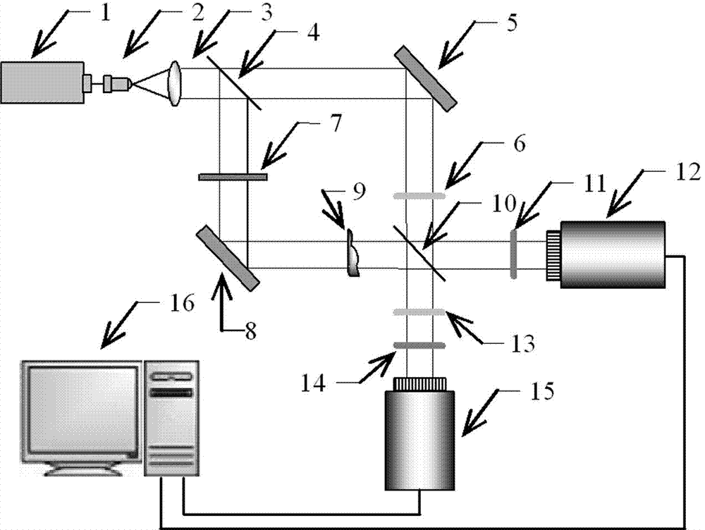
The invention relates to a double charge-coupled-device (CCD) single-exposure coaxial digital holographic record device, and belongs to the technical field of digital holography. The device utilizes double CCD mirror image overlap union record and single step phase shift cepstrum technology, achieves real-time record and reproduction of the coaxial digital holography, and can be used for dynamical measurement of small transparent phase position objects such as plankton. The basic principle of the device includes that a laser emitted by a laser device is divided into two beams after beam expansion and collimation, wherein one beam of the laser vertically irradiates the transparent phase position objects to form object light, after the other beam of the laser passes through a one half wave plate, the polarization direction is rotated by 90 degrees, the other beam serves as reference light, and at the moment, the polarization directions of the object light and the reference light are orthogonal; wave combination is conducted through a beam splitter, one of the two beams of the laser is recorded by a first CCD camera after polarization inspection and interference through a polarization analyzer, after the other one of the two beams of the laser passes through a one quarter wave plate, the phase position of the reference light is delayed by one half of pi, the phase position of the object light is not changed, and the other one of the two beams of the laser is recorded by a second CCD camera after polarization inspection and interference through the polarization analyzer; and a computer reads and reproduces the three-dimensional shapes of measured objects in real time.

Description

technical field [0001] The invention belongs to the technical field of digital holography, and in particular relates to a coaxial digital holographic recording device based on dual CCD image overlap adjustment and single exposure. Background technique [0002] Digital holography is a new coherent imaging technology that combines traditional optical holography and modern computer digital processing technology. The outstanding advantage of digital holography technology is that it can use the interference principle of light to obtain the complex amplitude of the wavefront of the measured object through a simple hardware system, so as to perform non-contact real-time three-dimensional imaging and measurement of the object. Therefore, this technology can be widely used in microscopic observation, microelectromechanical and micro-optical analysis, microbial phase-contrast microscopic imaging, vibration deformation measurement and information encryption, etc. [0003] In actual de...

Claims


Application Information

Patent Timeline
Patent Type & Authority Applications(China)
IPC IPC(8): G03H1/12G03H1/22
Inventor 潘卫清潘云范玉峰朱勇建王宇
Owner ZHEJIANG UNIVERSITY OF SCIENCE AND TECHNOLOGY
Learn More