
LED (Light-Emitting Diode) lamp tube

A technology of LED tube lamp and LED chip, which is applied to the cooling/heating device of lighting device, lighting and heating equipment, portable lighting device, etc., can solve the problems of inability to vacuumize, glare, poor sealing, etc., to improve the comfort of use , the effect of reducing the rise and improving the service life

Inactive Publication Date: 2013-04-10
浙江榆阳电子股份有限公司
View PDF10 Cites 12 Cited by
  • Summary
  • Abstract
  • Description
  • Claims
  • Application Information

AI Technical Summary

Problems solved by technology

[0004] 1. The strip-shaped heat-dissipating profile and the PC light-emitting strip are fixed through the card slot, which has poor sealing performance and cannot be vacuumed, and the thermal conductivity of the air is poor, resulting in the heat generated by the drive circuit and the LED light source when working cannot be dissipated in time, and the temperature rise is high. Affect the service life
[0005] 2. When the LED chip in the LED light source is fixed, its substrate is connected to the aluminum substrate (LED chip die-bonding bracket) through materials such as silver paste or gold-tin alloy, which makes the Most of the light is absorbed by the LED chip fixing material, which reduces the light extraction efficiency of the LED chip
[0006] 3. The luminous angle is 120°, the lighting comfort is poor, and the glare is serious

Method used


Image

  • LED (Light-Emitting Diode) lamp tube
  • LED (Light-Emitting Diode) lamp tube
  • LED (Light-Emitting Diode) lamp tube

Examples


Embodiment

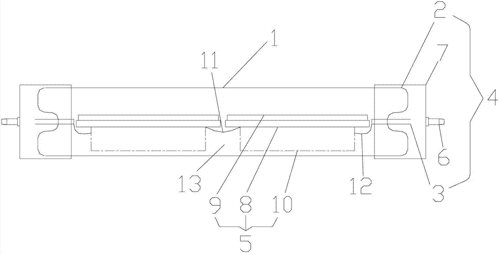
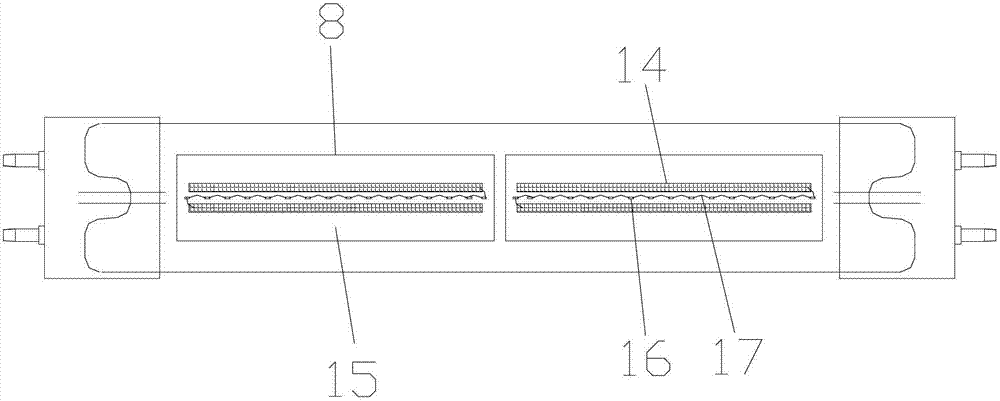
[0031] Example: an LED tube lamp, such as figure 1 or image 3 As shown, it includes a light-transmitting tube 1 (the light-transmitting tube is a transparent glass tube or a transparent frosted glass tube), an LED lighting module 5 arranged in the light-transmitting tube 1, and the LED lighting module 5 includes an LED light source 9. The circuit board 8 electrically connected to the LED light source, and the driver 10 electrically connected to the circuit board. The material of the circuit board 8 is transparent ceramic or glass or epoxy resin. The LED lighting module 5 is at least one set (usually, two or more than two groups are better). When the LED lighting module 5 is two or more than two sets, it is adjacent to the LED lighting module 5 Are connected by an electrical connection line 11. The driver 10 is connected to an electrical lead wire 3 via an AC power input line 12, and the electrical lead wire 3 is connected to a conductive terminal 6 to connect to an external po...


PUM


Abstract

The invention relates to an LED (Light-Emitting Diode) lamp tube which is characterized by comprising a transparent lamp tube, an LED illumination module and end covers, wherein the LED illumination module is arranged in the transparent lamp tub; both ends of the transparent lamp tube are respectively provided with stems; the end covers cover the peripheries of the stems; the stems are in vacuum seal fit with the transparent lamp tube; and vacuum sealed cavities formed by the stems and the transparent lamp tube are filled with inert gas. The LED lamp tube has the beneficial effects that 1, the stems are in vacuum seal fit with the transparent lamp tube and the inert gas is filled, so that heat of the LED illumination module arranged in the transparent lamp tube is rapidly dissipated by the inert gas, the rising amplitude of temperature rising is reduced and the service life is prolonged; 2, a radiator is avoided being used, the weight is reduced and cost is reduced; 3, in an LED light emitting source, except an LED chip, other components and fixing glue are all made of light transmitting materials, thus favorably enabling a light emitting angle of the LED chip to be equal to 4pi, avoiding dizziness and improving use comfort.

Description

Technical field [0001] The invention relates to an LED tube lamp. Background technique [0002] The existing LED tube lamp includes a lamp tube, a radiator and an LED light source arranged in the lamp tube, the LED light source is electrically connected with a driving circuit, and the driving circuit is arranged in the heat sink. The lamp tube is composed of a strip-shaped heat dissipation profile and a PC light-emitting strip, and the strip-shaped heat-dissipating profile and the PC light-emitting strip are fixed by a card slot. The LED light source is fixed on the strip heat dissipation profile through the aluminum substrate. [0003] The existing LED tube lights have the following technical defects: [0004] 1. The strip-shaped heat dissipation profile and the PC light-emitting strip are fixed by the card slot, which is poorly sealed and cannot be vacuumed, and the thermal conductivity of the air is poor. As a result, the heat generated by the driving circuit and the LED light s...

Claims


Application Information

Patent Timeline
Patent Type & Authority Applications(China)
IPC IPC(8): F21S2/00F21V29/00F21V9/08F21V1/16F21Y101/02F21K9/27F21V29/503F21Y115/10
Inventor 汪正林方洁苗
Owner 浙江榆阳电子股份有限公司
Learn More