Photovoltaic triggering circuit, optical signal receive control equipment and decoding method thereof

A technology of receiving control and photoelectric triggering, applied in the field of optical communication, can solve the problems of unstable signal, high number of high levels, slow data transmission speed, etc., and achieve the effect of low power consumption

Active Publication Date: 2014-04-16
KUANG CHI INTELLIGENT PHOTONIC TECH
View PDF6 Cites 0 Cited by
  • Summary
  • Abstract
  • Description
  • Claims
  • Application Information

AI Technical Summary

Problems solved by technology

[0007] The decoding method corresponding to the above-mentioned existing encoding method needs to output and detect a large number of high levels, resulting in a very unstable signal, and the overall signal sending time and receiving time are long, and the data transmission speed is slow

Method used


Image

  • Photovoltaic triggering circuit, optical signal receive control equipment and decoding method thereof
  • Photovoltaic triggering circuit, optical signal receive control equipment and decoding method thereof
  • Photovoltaic triggering circuit, optical signal receive control equipment and decoding method thereof

Examples


Embodiment 1

[0077] Let low level represent 00, 1 high level represent 01, 2 high levels represent 10, 3 high levels represent 11, the signal sending period is fixed at 59ms, and the delay time of high level is 5ms, then press the For a schematic diagram of the signal sent by the encoding method, see Figure 4 , the signal schematic diagram of the first preferred embodiment of the present invention, the signal of 2 bits is represented by a low level, the number of high levels is reduced, and the signal is more stable, and at the same time, the total transmission time of the signal will not change due to different transmission signals, The signal sent by the optical signal receiving control device in this embodiment is 01110010, and the optical signal receiving control device decodes the signal:

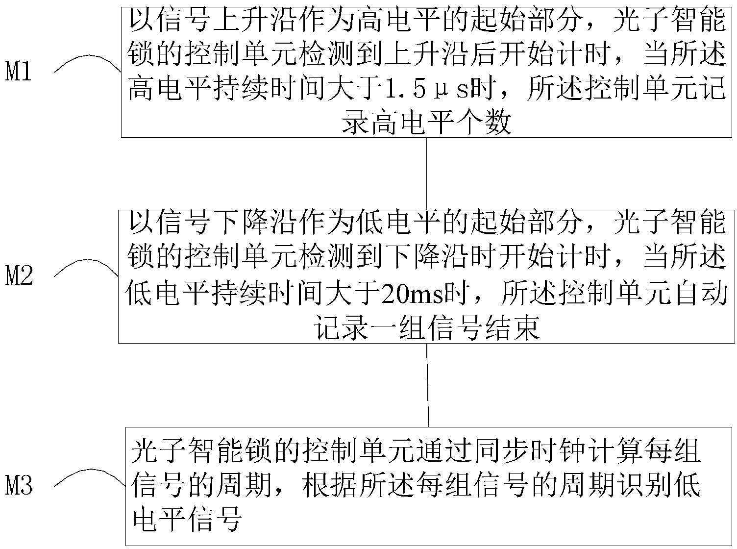
[0078] M1. With the rising edge as the starting part of the high level, the optical signal receiving control device starts timing after detecting the rising edge. When the high level lasts for 1.5...

Embodiment 2

[0082]Let 1 high level represent 00, 2 high levels represent 10, 3 high levels represent 01, 4 high levels represent 11, the signal sending cycle is fixed at 63ms, and the delay time of high level is 3ms, then The schematic diagram of the signal sent by this encoding method can be found in Figure 5 , the signal schematic diagram of the second preferred embodiment of the present invention, the signal sent by this embodiment is 00100111, and the optical signal receiving control device decodes the signal:

[0083] M1. With the rising edge as the starting part of the high level, the optical signal receiving control device starts timing after detecting the rising edge. When the high level lasts for 1ms, the optical signal receiving control device records the number of high levels of the signal They are 1, 2, 3, and 4 respectively. When a high-level signal appears within 40ms after a group of signals ends, the optical signal receiving control device corrects the clock according to ...


PUM


Abstract

The invention discloses a photovoltaic triggering circuit which comprises a photoelectric conversion unit, an isolator and an output end, wherein the photoelectric conversion unit is used for converting optical pulse into an electric pulse signal, the isolator is used for generating potential difference through the electric pulse signal so as to release an electrical signal, and the output end is used for triggering a power supply unit of optical signal receive control equipment to be electrified according to the electrical signal. The invention also discloses the optical signal receive control equipment additionally provided with the photovoltaic triggering circuit, the power supply unit of the optical signal receive control equipment can be electrified so as to start when an optical pulse signal is received, the power supply unit is in a dormant state with low power consumption when the optical pulse signal is not available, and the optical signal receive control equipment with the photovoltaic triggering circuit is energy-saving and environment-friendly; and in addition, the invention also discloses a decoding method of the optical signal receive control equipment, and the decoding method can notably improve the safety performance of the optical signal receive control equipment.

Description

technical field [0001] The invention relates to the field of optical communication, in particular to a photoelectric trigger circuit, an optical signal receiving and controlling device, and a decoding method for the optical signal receiving and controlling device. Background technique [0002] Wireless optical communication technology, also known as visible light communication, communicates through high-frequency flickering of LED light sources. Light represents 1, and no light represents 0. Its transmission rate is up to gigabits per second. Wireless optical communication technology can be used to make wireless optical encryption keys because its data is not easy to be interfered and captured, and optical communication equipment is simple to manufacture and should not be damaged or degaussed. Compared with microwave technology, wireless optical communication has quite rich spectrum resources, which is unmatched by general microwave communication and wireless communication; ...

Claims


Application Information

Patent Timeline
Patent Type & Authority Patents(China)
IPC IPC(8): G07C9/00
Inventor 刘若鹏栾琳孙文超李蔚
Owner KUANG CHI INTELLIGENT PHOTONIC TECH
Why Eureka
Try Eureka