Dual-drive tunnel heading machine speed reducer

A technology of tunnel boring machine and reducer, which is applied in mechanical equipment, gear transmission, belt/chain/gear, etc., to achieve the effect of improving load sharing performance, convenient installation and maintenance, and small size

Inactive Publication Date: 2013-04-03
DALIAN UNIV OF TECH
View PDF5 Cites 7 Cited by
  • Summary
  • Abstract
  • Description
  • Claims
  • Application Information

AI Technical Summary

Problems solved by technology

[0005] The present invention aims to solve the shortcomings of the existing tunnel boring machine reducer, and adopts a double-input differential structure and an N-W type transmission output mechanism. The gears are externally meshed with three large gears distributed around the circumference to realize power transmission and flow splitting. The large gears drive the third-stage gears to rotate through the common shaft, and the gears are internally meshed with the public internal ring gear to realize confluence output. During normal operation, the large motor drives and the small motor Braking, the rated power output of the large motor, when the resistance moment of the earth and rocks is too large or even collapses, the large motor and the small motor are driven at the same time to realize the escape of the tunnel boring machine, and the second and third stages adopt N-W transmission form, which simplifies the structure and reduces the The number of meshing points improves the load sharing performance. The invention also has the advantages of large reduction ratio, small volume, light weight, and simple structure, and can realize low-speed high-torque output

Method used


Image

  • Dual-drive tunnel heading machine speed reducer
  • Dual-drive tunnel heading machine speed reducer
  • Dual-drive tunnel heading machine speed reducer

Examples


Embodiment approach 1

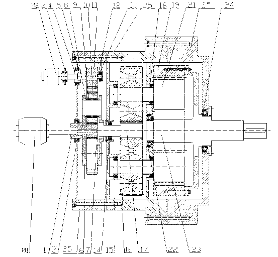
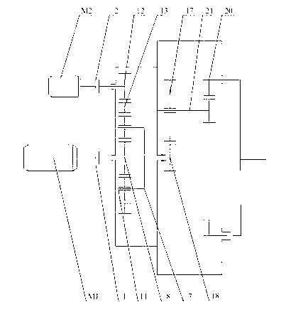
[0023] The brakes 2 are all in the closed state, the power input component IM1 transmits the power to the input sun gear 8, the sun gear drives the input planetary gear 10 meshed with it, the input planetary gear 10 undergoes self-propagation and revolution, and transmits the power to the planetary carrier 6, the planetary The frame 6 is used as the input of the second stage to drive the pinion shaft 17 to rotate, and the pinion shaft 17 is meshed with three large gears 16 evenly distributed on the circumference for transmission to realize shunting. The interference fit of the large gear 16 is connected to the output gear shaft 21 Circumferential transmission cooperation, the output gear shaft 21 and the ring gear 19 are meshed for transmission to realize confluence, the ring gear 19 and the power output shaft 23 are fixedly connected in the circumferential direction, thereby realizing power output, and the power output shafts of multiple speed reducers 26 The power is transmit...

Embodiment approach 2

[0025]Coupling Ⅰ1 and brake 2 are both in the disengaged state, power input component IM1 and power input component IIM2 rotate in the same direction, power input component IM1 transmits power to the input sun gear 7, and power input component IIM2 transmits power to the input external gear 11 And transmitted to the input ring gear 12, the rotation of the input sun gear 7 and the input ring gear 12 are opposite, through the confluence of the differential planetary gear train, the planet carrier 6 is used as the input of the second stage, driving the pinion shaft 17 to rotate, the pinion shaft 17 The gear shaft 17 is meshed with three large gears 16 evenly distributed on the circumference for transmission to realize flow splitting. The interference fit of the large gears 16 is connected to the output gear shaft 21 for transmission in the circumferential direction, and the output gear shaft 21 is meshed with the ring gear 19 for transmission. To achieve confluence, the ring gear ...


PUM


Abstract

The invention discloses a dual-drive tunnel heading machine speed reducer. The speed reducer adopts a dual-input differential motion structure and an N-W type transmission output mechanism, the input motive power is converged through a differential motion mechanism and is output to a second-stage pinion through a connecting shaft, the pinion is externally engaged with three gearwheels in circumference distribution for realizing the power transmission and flow division, the gearwheels drive the rotation of a third-stage gear through a public shaft, the gears are internally engaged with a public inner tooth ring for realizing the convergence output, during the normal work, a large motor is used for driving, a small motor is used for braking, the large motor outputs at the rated power, when over-large soil and rock resistance moment or even collapse occurs, the large motor and the small motor are simultaneously used for driving, the difficulty escaping of a tunnel heading machine is realized, and in addition, the second and third states adopt the N-W type transmission mode. The dual-drive tunnel heading machine speed reducer has the advantages that the structure is simplified, the engagement point number is reduced, the uniform load performance is improved, the advantages of great reduction ratio, small size, light weight, simple structure and the like are also realized, and the low-speed large-torque output can be realized.

Description

technical field [0001] The invention relates to a speed reducer for a tunnel boring machine, in particular to a speed reducer for a tunnel boring machine. Background technique [0002] Tunnel boring machine is the main construction machine in shield construction. Because shield construction has the advantages of safety, reliability, small environmental impact, low labor intensity, less earthwork, and high efficiency, it is widely used in urban rail, water conservancy, municipal engineering, mines, and highways. , Railway tunnels and other fields are widely used. Since the tunnel boring machine is often constructed in a complex and harsh working environment, the drive and transmission system of the tunnel boring machine are required to be able to withstand heavy loads and large impacts, and to have high power, low speed and high torque output, etc. function; and these requirements have relatively high requirements for the material, manufacturing and processing of the transmi...

Claims


Application Information

Patent Timeline
Patent Type & Authority Applications(China)
IPC IPC(8): F16H1/28
Inventor 孙伟魏静涂文平王庆国丁鑫
Owner DALIAN UNIV OF TECH
Why Eureka
Try Eureka