Driving circuit and driving method of external rotor electronic control type fan adjuster

An electronic control and drive circuit technology, applied in machine/engine, pump control, mechanical equipment, etc., can solve problems such as inability to achieve isolated speed regulation, no overvoltage protection, and easy burnout of the fan power supply system

Active Publication Date: 2015-07-08
HANGZHOU DUNLI ELECTRIC APPLIANCES
View PDF9 Cites 0 Cited by
  • Summary
  • Abstract
  • Description
  • Claims
  • Application Information

AI Technical Summary

Problems solved by technology

Its disadvantages: it is impossible to achieve isolated speed regulation, and it does not have good overvoltage protection, which makes the fan power system easy to burn out
Its disadvantages: it is not suitable for the DC brushless external rotor fan with AC power input in this application

Method used


Image

  • Driving circuit and driving method of external rotor electronic control type fan adjuster

Examples


Embodiment 1

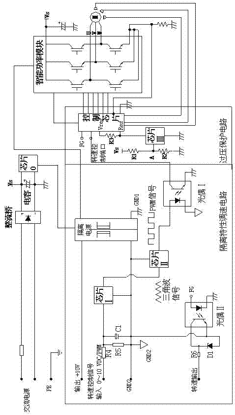
[0011] Embodiment 1: with reference to attached figure 1 . An external rotor electronically controlled fan regulator drive circuit is composed of an isolation characteristic speed regulation circuit and an overvoltage protection circuit; the power output terminal of the isolated power supply in the isolation characteristic speed regulation circuit outputs +10V power supply, and the ground terminal GND2 of the isolation power supply Connect to the ground terminal of operational amplifier chip Ⅰ, the ground terminal of comparator chip Ⅱ, the signal output terminal of optocoupler Ⅱ, the negative pole of capacitor C1, the negative pole of diode D1, the positive pole of capacitor C1 is connected to the signal input terminal of operational amplifier chip Ⅰ, and the positive pole of diode D1 is connected to the speed Output terminal, the signal input terminal of the optocoupler II is connected to the FG signal terminal, the signal terminal of the isolated power supply is connected t...

Embodiment 2

[0012] Embodiment 2: On the basis of Embodiment 1, a driving method for an external rotor electronically controlled fan regulator drive circuit, using AC / DC conversion chip 0 to generate power with isolation characteristics for operational amplifier chip I and comparator chip Ⅱ provides working power, and the triangular wave signal generated by the operational amplifier chip Ⅰ enters the comparator chip Ⅱ for signal processing to generate a PWM signal. To realize the speed regulation function, the fan speed signal FG is fed back to the fan user power system in real time through the optocoupler II; the voltage detection circuit is used to detect the rectified DC voltage VS at the intelligent power control module terminal in real time, when the rectified DC voltage VS at the intelligent power control module terminal When it rises, the voltage at point A of the signal input terminal of the comparator chip III also rises accordingly. When the rectified DC voltage VS at the intellig...


PUM


Abstract

The invention relates to a driving circuit and a driving method of an external rotor electronic control type fan adjuster. An AC / DC (alternating current / direct current) conversion chip is utilized for generating a power supply with an isolation property so as to provide a working power supply for a chip operational amplifier and a comparator, the chip operational amplifier is utilized for producing a triangular wave signal, then the triangular wave signal enters into a chip of the comparator for performing signal processing, and then a PWM (pulse width modulation) signal is produced. The PWM signal is connected with a rotational speed control port of a fan control chip after passing through an optocoupler I for realizing the speed regulation function; a fan rotational speed signal (FG) can be fed back to a power supply system of a fan user in a real-time manner through an optocoupler II; a voltage detection loop is utilized for real-time detection of VS voltage, when the VS voltage is increased, A voltage is increased accordingly, when the VS voltage is increased to a set value, the A voltage achieves reference voltage of a chip III (the comparator), then the voltage at an RES (resistor) terminal of the control chip becomes low level, then the control chip can immediately cut off a driving signal required for a power module, a fan can consume U1 by utilizing a winding of the fan, and then the U1 can be reduced till that the U1 is the same with the direct current voltage after rectification, so that overvoltage protection of the loop can be realized.

Description

technical field [0001] The invention relates to an external rotor electronically controlled fan regulator drive which can not only fundamentally solve the burning of the power supply system of the outer rotor fan, but also avoid the reverse voltage generated by the back electromotive force of the fan itself from damaging the intelligent power control module. A circuit and a driving method belong to the field of manufacturing speed regulating circuits of external rotor fans. Background technique [0002] CN102364114A, the name "a remote control speed-adjustable external rotor axial flow fan", including fan blades, mesh cover, junction box, motor, is characterized in that: the junction box includes a signal receiving module, a transformer rectifier circuit, a decoding circuit, Motor control circuit, control signal transmitting circuit, control signal receiving circuit, motor control circuit, the transformer and rectifier circuit converts the alternating current into a smaller ...

Claims


Application Information

Patent Timeline
Patent Type & Authority Patents(China)
IPC IPC(8): F04D27/00
Inventor 孙勇屈刚
Owner HANGZHOU DUNLI ELECTRIC APPLIANCES
Why Eureka
Try Eureka