Crane protective device and crane
A protective device and crane technology, which is applied in the direction of cranes, etc., can solve the problems of small working range of the boom, impact of steel wire rope and pulley, impact of heavy objects on the frame, etc., so as to improve working stability, stable and reliable work, and high degree of automation Effect
- Summary
- Abstract
- Description
- Claims
- Application Information
AI Technical Summary
Problems solved by technology
Method used
Image
Examples
Embodiment 1
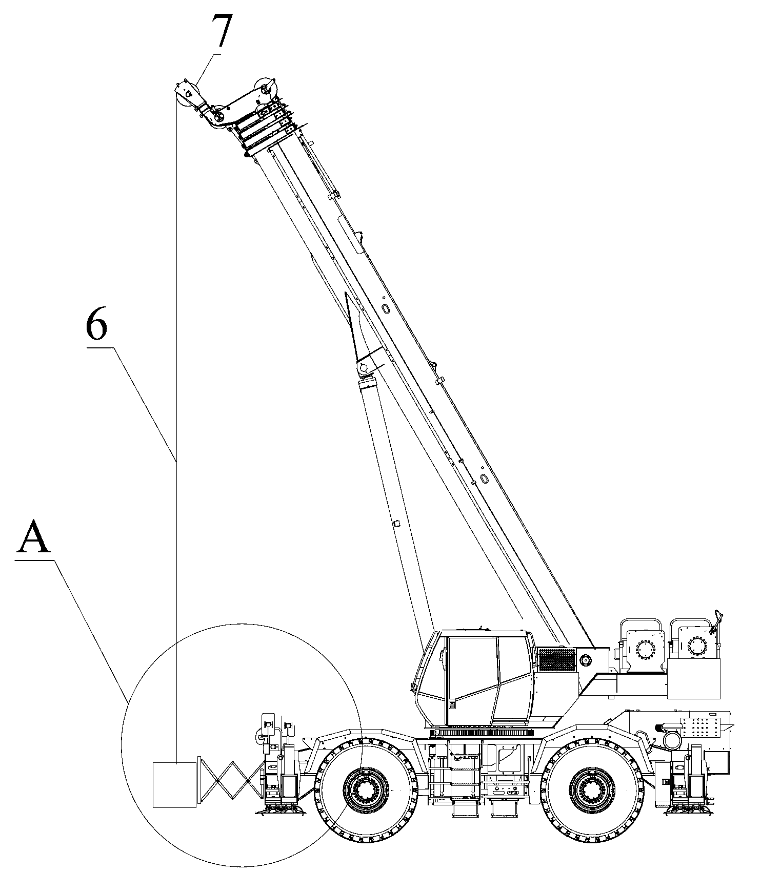
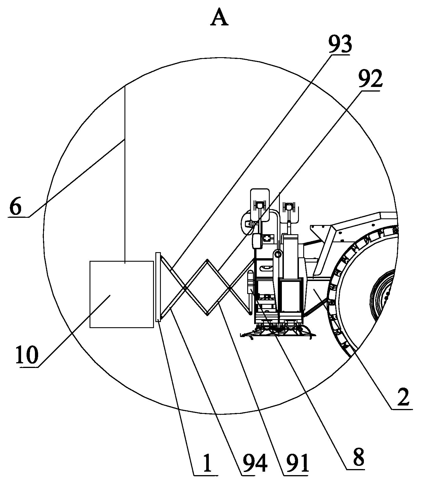
[0039] In this embodiment, the telescopic mechanism includes at least one rod set and at least one telescopic oil cylinder, each of the rod sets includes two rods that cross in an "X" shape and are hinged at the intersection point; The group is hinged to form a telescopic frame through the ends of the adjacent rods; one end of the telescopic oil cylinder is connected to one of the rods in the rod group, and the other end is installed on the frame of the crane. The telescopic oil cylinder drives the expansion and contraction of the telescopic frame; one end of the telescopic frame is connected with the protective block 1, and the other end is connected with the vehicle frame 2 of the crane.
[0040] Such as figure 1 and figure 2 As shown, the boom 11 lifts the weight 10 through the pulley 7 and the wire rope 6, and the telescopic mechanism includes the first rod 91, the second rod 92, the third rod 93, the fourth rod 94 and the telescopic oil cylinder 8, the first rod 91 and...
Embodiment 2
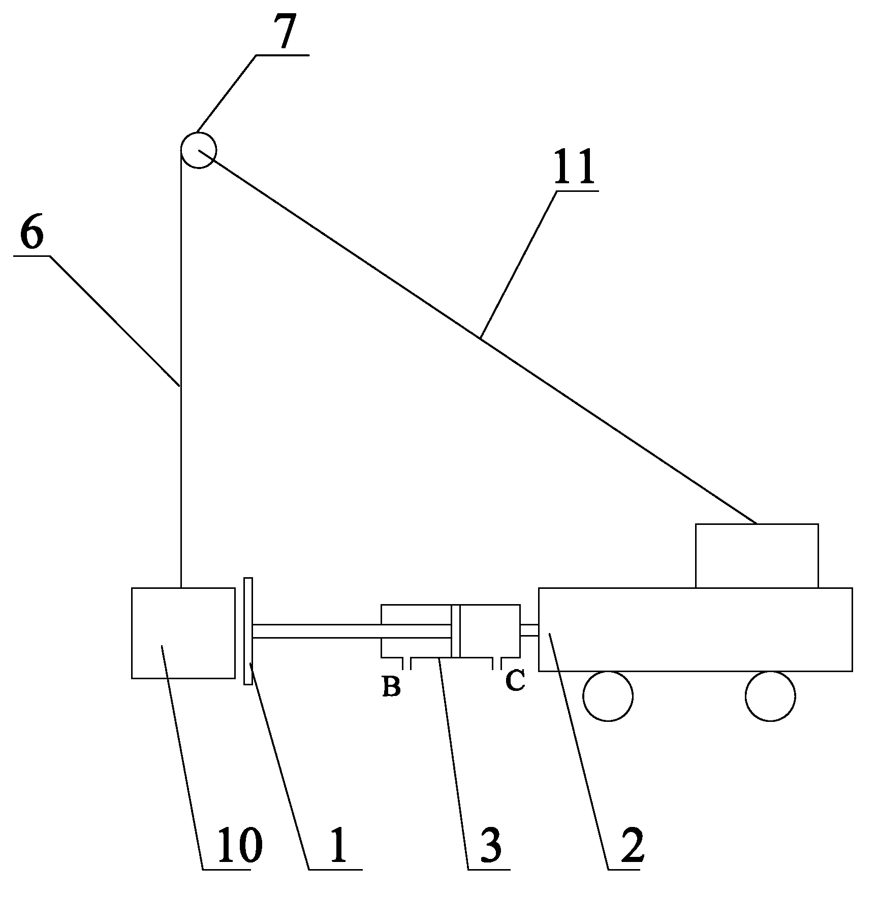
[0045] In this embodiment, the telescopic mechanism includes a first pressure cylinder 3, one end of the first pressure cylinder 3 is fixed on the frame 2 of the crane, and the other end of the first pressure cylinder 3 is connected to the The protective block 1 is connected, and the first pressure cylinder 3 can drive the protective block 1 to expand and contract.
[0046] Such as image 3 As shown, the boom 11 lifts the weight 10 through the pulley 7 and the wire rope 6. The telescopic mechanism is the first pressure cylinder 3, the cylinder barrel of the first pressure cylinder 3 is fixed on the vehicle frame 2, and the piston rod of the first pressure cylinder 3 Connected with the protective block 1, the first pressure cylinder 3 can be a pneumatic cylinder or a hydraulic cylinder. When the piston rod is stretched out, the C port connected with the rodless chamber of the cylinder is the inlet, and the B port connected with the rod chamber of the cylinder is the outlet; wh...
Embodiment 3
[0050] On the basis of the second embodiment, an elastic element is further arranged between the first pressure cylinder 3 and the protection block 1 .
[0051] Such as Figure 4 shown in image 3 Based on the illustrated embodiment, a spring 4 is sheathed on the piston rod between the protective block 1 and the cylinder barrel of the first pressure cylinder 3 .
[0052] The boom 11 lifts the heavy object 10 through the pulley 7 and the wire rope 6. When the crane is driving with the heavy object, the oil (air) enters the C port, and the oil (air) discharges from the B port. The pressure oil (air) pushes the piston and the piston rod to extend. out, the piston rod drives the protective block 1 to move forward. When the protective block 1 is close to the heavy object 10, the C port stops oil (air) inlet, and the protective block 1 just touches the heavy object 10 at this moment. Due to the supporting force of the protective block 1, the heavy object 10 cannot swing in the fr...
PUM
 Abstract
Description
Claims
Application Information
 - Generate Ideas
- Intellectual Property
- Life Sciences
- Materials
- Tech Scout
- Unparalleled Data Quality
- Higher Quality Content
- 60% Fewer Hallucinations
Browse by: Latest US Patents, China's latest patents, Technical Efficacy Thesaurus, Application Domain, Technology Topic, Popular Technical Reports.
© 2025 PatSnap. All rights reserved.Legal|Privacy policy|Modern Slavery Act Transparency Statement|Sitemap|About US| Contact US: help@patsnap.com


