
Broken end suction device of tail yarn removing machine

A technology of suction device and cleaning machine, which is applied in the directions of transportation and packaging, transportation of filamentous materials, and processing of thin materials, etc. The problem is to improve the efficiency of tail yarn removal, facilitate the search for broken yarn ends, and reduce the length of broken ends.

Active Publication Date: 2013-04-03
CMT HICORP MACHINERY QINGDAO
View PDF4 Cites 2 Cited by
  • Summary
  • Abstract
  • Description
  • Claims
  • Application Information

AI Technical Summary

Problems solved by technology

In the actual operation process, some tail yarn bobbins often cause longer tail yarn breakage due to operational reasons or the weight of the yarn. If such bobbins are directly put into the tail yarn removal machine, the up and down movement of the machine itself is limited. , it often happens that the suction pipe of the tail yarn removal machine cannot find the broken yarn end, and the tail yarn cannot be cleaned

Method used


Image

  • Broken end suction device of tail yarn removing machine
  • Broken end suction device of tail yarn removing machine

Examples


Embodiment Construction

[0019] The present invention will be further described in detail below in conjunction with the accompanying drawings and specific embodiments, but the present invention is not limited to these embodiments.

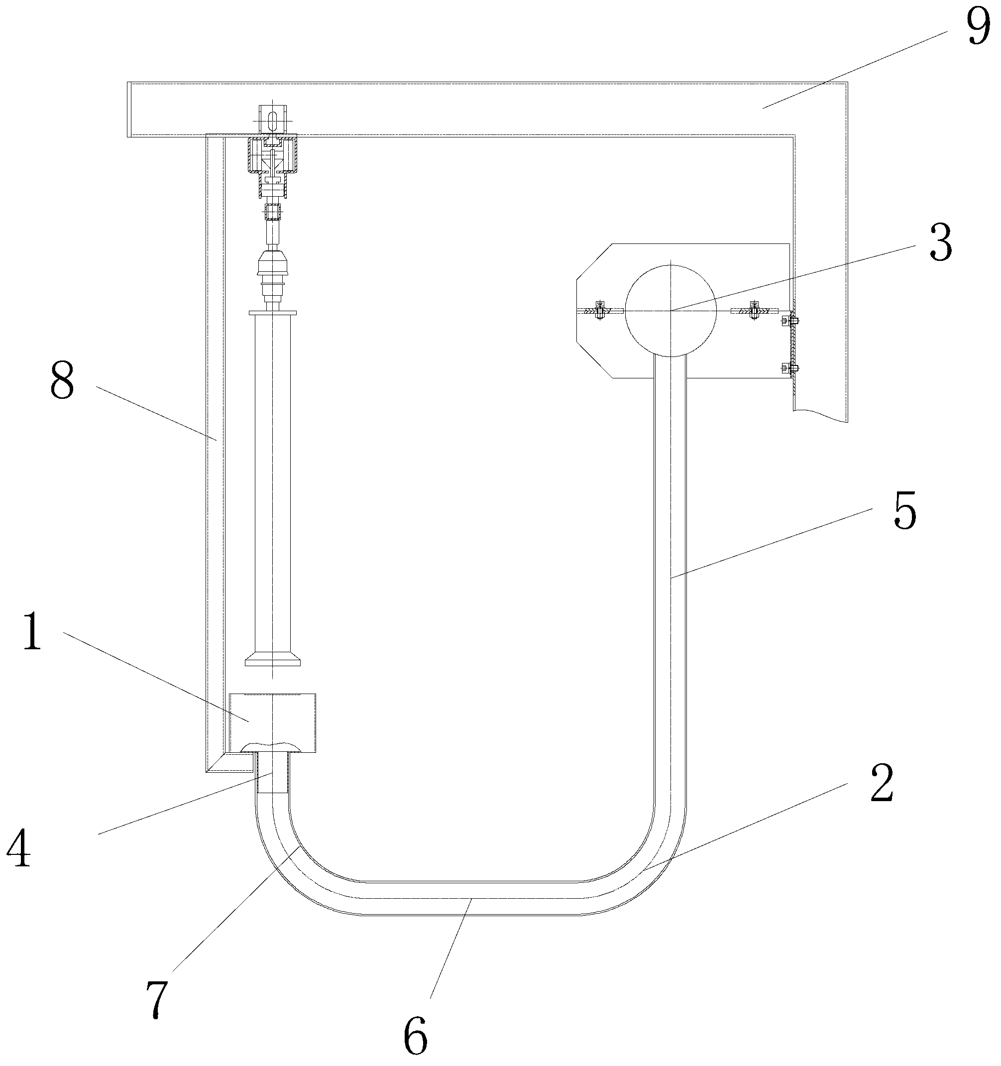
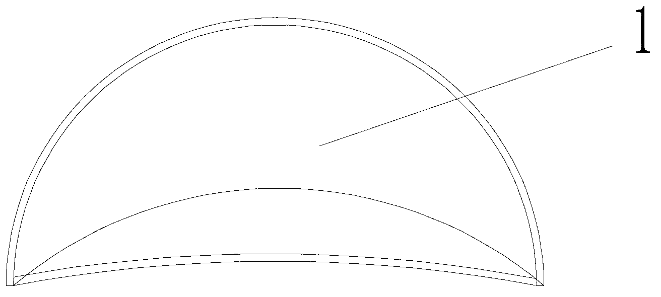
[0020] Such as figure 1 As shown, a broken end suction device of a tail yarn clearing machine includes a broken end suction assembly and a drive unit, and the drive unit includes a drive motor and a fan, and the drive motor and the blower fan are all arranged in the tail yarn clearer 9; The suction breakage assembly includes a suction nozzle and a No. 1 suction pipe 2, one end of the No. 1 suction pipe 2 is fixedly connected to the suction nozzle, and the other end is connected to the No. 2 suction pipe 3 arranged on the tail yarn clearing machine 9 The No. 2 suction pipe 3 is connected to the air suction port of the above-mentioned fan; the driving motor drives the impeller in the fan to rotate to generate rotating wind force, which is transmitted to the suction nozzle th...


PUM


Abstract

The invention discloses a broken end suction device of a tail yarn removing machine. The broken end suction device comprises a broken end suction component and a driving unit, wherein the driving unit comprises a driving motor and a fan; the driving motor and the fan are both arranged in the tail yarn removing machine; the broken end suction component comprises a suction nozzle and a first suction pipe; one end of the first suction pipe is fixedly connected with the suction nozzle, and the other end of the first suction pipe is communicated with a second suction pipe on the tail yarn removing machine; and the second suction pipe is connected with an exhaust opening of the fan. The broken end suction device can suck the broken ends on a spool under the condition that the tail yarn spool moves; the cotton yarns are snapped under the combined action of suction force and pulling force; the broken end length of the tail yarn is reduced; the tail yarn removing machine can conveniently search the tail yarn broken ends; and the tail yarn removing efficiency is improved.

Description

technical field [0001] The invention belongs to the field of textile machinery equipment, and in particular relates to a broken end suction device for a tail yarn clearing machine. Background technique [0002] In the textile industry, the removal of tail yarns is mostly done by hand, that is, the tail yarns are cut off from the roving bobbin one by one with scissors. This method is time-consuming, laborious, and dangerous. In order to save labor and time, many enterprises often choose direct Discarding the tail yarn caused a great waste of resources, so a tail yarn removal machine appeared on the market, which is mainly used to absorb the tail yarn on the roving bobbin used by the spinning frame and the sticky strip in the thick-fine coupling system. The waste flowers on the roving machine are automatically cleared, and then directly used for the automatic spinning of the roving frame through the automatic conveying system. The appearance of the tail yarn clearing machine g...

Claims


Application Information

Patent Timeline
Patent Type & Authority Applications(China)
IPC IPC(8): B65H73/00
Inventor 崔桂华郭加阳李建霞周春娟尹怀秀赵天洁李凤翥
Owner CMT HICORP MACHINERY QINGDAO
Learn More