A magnetic field modulation hybrid excitation motor and its multi-operating wave design method

A hybrid excitation motor and magnetic field modulation technology, which is applied in the field of rail transit and electric vehicles, to achieve the effects of reducing the reluctance of the excitation magnetic field, enhancing the magnetic field adjustment energy, and reducing the length of the end

Active Publication Date: 2021-05-25
JIANGSU UNIV
View PDF7 Cites 0 Cited by
  • Summary
  • Abstract
  • Description
  • Claims
  • Application Information

AI Technical Summary

Problems solved by technology

In addition, due to its many excitation sources, the mechanical strength, temperature rise, and processing technology brought about by the special structure and electromagnetic design are also issues that need to be considered during design.

Method used


Image

  • A magnetic field modulation hybrid excitation motor and its multi-operating wave design method
  • A magnetic field modulation hybrid excitation motor and its multi-operating wave design method
  • A magnetic field modulation hybrid excitation motor and its multi-operating wave design method

Examples


example 1

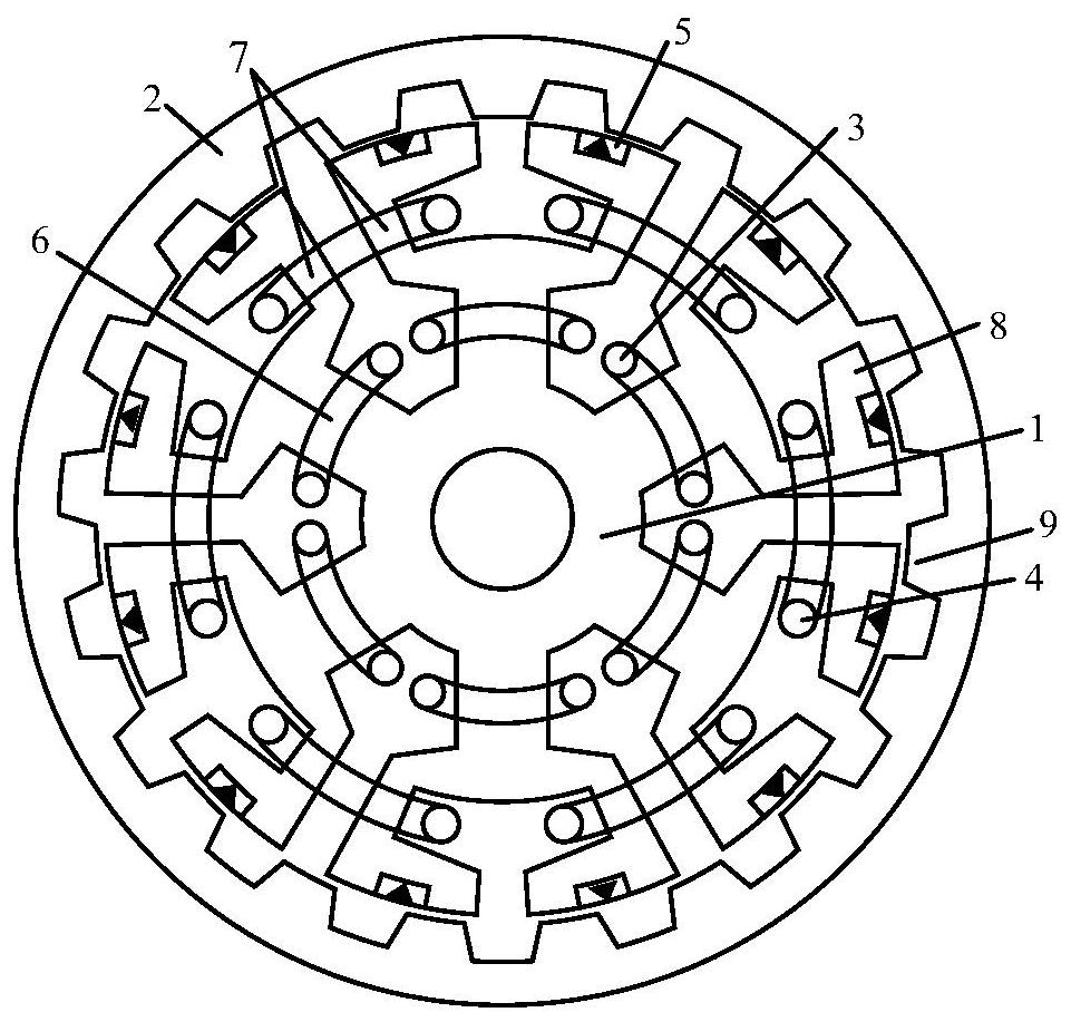
[0084] figure 1 It is a structural schematic diagram of a hybrid excitation motor according to an embodiment of the present invention. Such as figure 1 As shown, the motor is a three-phase motor, including a stator (1) and a rotor (2), which are installed coaxially, and the stator (1) is sleeved in the rotor. The material of the stator core is the same as that of the rotor (2), which is formed by laminating silicon steel sheets. There is a groove on the surface of each stator tooth (6), which splits the end of the stator tooth (6) into two modulation teeth (7), and the excitation winding (4) is placed in the groove of the stator tooth, and the excitation adopts double-layer centralized Wound on two adjacent modulated teeth (7) split by different stator teeth (6), the armature winding (3) is placed in the open slot of the stator core, and is wound on the stator teeth ( 6) on. Among them, the excitation winding (4) is supplied with direct current, and the direction of the cu...

example 2

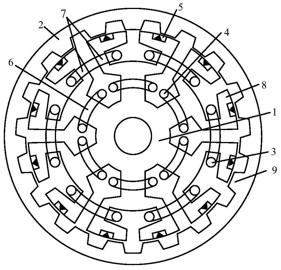
[0094] In another embodiment of the present invention such as figure 2 As shown, compared with this embodiment, the structure of the motor stator and rotor is exactly the same, but the installation positions of the armature winding (3), the field winding (4) and the permanent magnet (5) are different. In another embodiment, the armature The winding (3) is placed in the groove of the stator teeth, and the double-layer concentrated winding is on two adjacent modulation teeth split by different stator teeth; the excitation winding (4) is placed in the open slot of the stator core, The double-layer centralized winding is on a stator tooth (6); the magnetization direction of the permanent magnet (5) is radial magnetization, and the placement position is: two modulation teeth ( The polarities of the permanent magnets (5) on 7) are the same, and the polarities of the permanent magnets (5) on two adjacent modulating teeth (7) split by different stator teeth (6) are opposite.

[0095...


PUM


Abstract

The invention discloses a magnetic field modulation hybrid excitation motor and its multi-working wave design method. It is an open slot. A set of windings is distributed in the open slot of the stator core. It is wound on one stator tooth in a concentrated manner. A groove is opened on the outer surface of each stator tooth, and the other set of windings is placed in the groove of the stator tooth. Each The stator teeth are split into two modulating teeth through grooves, and a permanent magnet is placed on each modulating tooth, and the other set of windings is wound on two adjacent modulating teeth split by different stator teeth, and the The direction of magnetization is consistent with or opposite to the direction of the magnetic field formed by the field winding on the tooth. The permanent magnet magnetomotive force and the excitation magnetomotive force of the present invention are connected in parallel on the magnetic circuit and are independent of each other, so as to avoid the risk of irreversible demagnetization caused by the permanent magnet fed with the excitation current, and ensure the effective display of the magnetic adjustment ability.

Description

technical field [0001] The invention relates to a hybrid excitation motor and its multi-working wave design method, which belongs to the field of motors, and is particularly suitable for the application of electric vehicles requiring high torque and wide speed regulation range. In addition, according to the structure that all excitations are placed on the stator Features, suitable for long-distance rail transit. Background technique [0002] Compared with traditional electric excitation motors, permanent magnet motors have the advantages of large output torque and high efficiency, so they are widely used in various industries. However, due to the characteristics of the permanent magnet material itself, the permanent magnet magnetic field in the permanent magnet motor is relatively fixed, and the magnetic adjustment capability is limited. In order to improve the magnetic field adjustment ability of the motor and maintain a high output torque, the hybrid excitation motor came...

Claims


Application Information

Patent Timeline
Patent Type & Authority Patents(China)
IPC IPC(8): H02K21/22H02K3/20H02K21/04H02K1/17
CPCH02K1/17H02K3/20H02K21/04H02K21/227H02K2201/03H02K2213/03
Inventor 赵文祥蒋婷婷徐亮吉敬华
Owner JIANGSU UNIV
Why Eureka
Try Eureka