Heavy rotary supporting roller frame

A technology of rotating supporting rollers and supporting roller frames, which is applied in the field of machine tools, and can solve problems such as complex structure of supporting rollers, broken screw rods, and low service life, so as to overcome low utilization rate of equipment, facilitate installation and disassembly, and prolong service life Effect

Active Publication Date: 2013-04-03
四川德建机械有限公司
View PDF9 Cites 2 Cited by
  • Summary
  • Abstract
  • Description
  • Claims
  • Application Information

AI Technical Summary

Problems solved by technology

[0004] However, the existing technology represented by the above-mentioned patent documents still has the following defects in actual use: 1. Since the left inclined block and the right inclined block are relatively arranged, the supporting roller is arranged on the inclined surface, so this patent mainly It is suitable for supporting cylindrical metal parts, and it cannot support metal parts with large differences in specifications and models. Its strength is still low, and it cannot be used to support more than 150 tons of heavy metal workpieces; 3. The bracket adjusts the distance between the left inclined block and the right inclined block through the screw thread, so that the metal parts are placed on the bridge, and In the process of processing, it is often necessary to adjust the position of the metal parts. At this time, since the metal parts are pressed on the left and right inclined blocks, a large driving force is required to adjust successfully, which will not only cause great damage to the screw rod and thread Large wear and tear will reduce its service life. In serious cases, it will cause the screw rod to break and cause serious safety accidents; 4. During the processing process, it is necessary to repeatedly lift the V-shaped frame so that it can be rubbed away with the grinding head, which will not only cause great wear and tear on the oil cylinder. , will also lead to a reduction in the grinding accuracy of the metal parts; 5. The structure of the supporting wheel frame is complex, the cost is high, the wear between the parts is large, and the service life is low

Method used


Image

  • Heavy rotary supporting roller frame
  • Heavy rotary supporting roller frame
  • Heavy rotary supporting roller frame

Examples


Embodiment 1

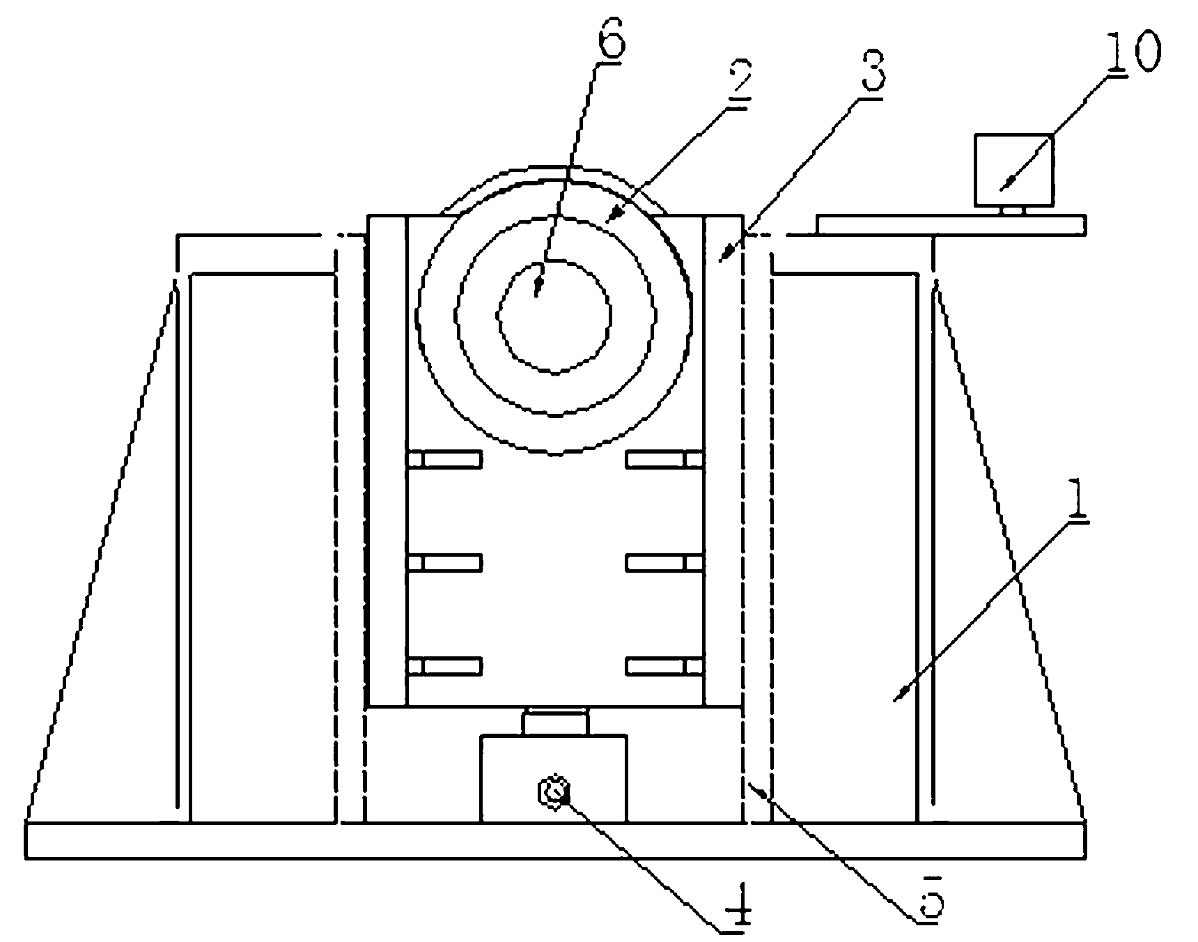
[0035] A heavy-duty rotating roller frame, comprising a base body 1, a decelerating motor, a supporting wheel 2 and a supporting wheel support frame 3, a groove is opened on the base body 1, and a self-locking jack 4 is fixedly arranged at the bottom of the groove, so that The self-locking jack 4 is fixedly connected to the bottom of the supporting roller support frame 3, and the supporting roller supporting frame 3 is slidably arranged in the groove; The supporting surface is higher than the supporting wheel support frame 3, and the power output shaft of the geared motor is connected with the supporting wheel 2.

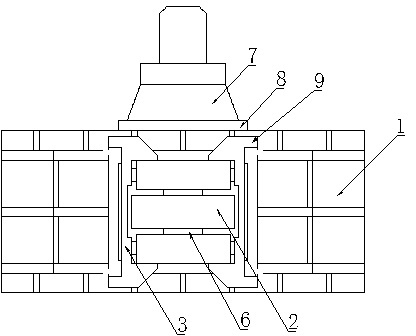
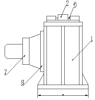
[0036] The preferred implementation mode of this embodiment is that the upper part of the supporting wheel support frame 3 is provided with an inner cavity, and a rotating shaft 6 is arranged between the two side walls of the inner cavity, and the two ends of the rotating shaft 6 move with the supporting wheel supporting frame 3 through bearings. connected, the supp...

Embodiment 2

[0046] This embodiment is basically the same as the above-mentioned embodiment, the main difference is: the base body 1 is a trapezoidal structure, the height of the base body 1 is 0.6m, the length of the upper side of the base body 1 is 0.8m, and the length of the lower side of the base body 1 is 1.2m. The thickness of the seat body 1 is 0.5m.

Embodiment 3

[0048] This embodiment is basically the same as the above-mentioned embodiment, the main difference is that: the upper side of the seat body 1 is provided with a limiting wheel 10 .

[0049] In the present invention, the working support surface of the support roller 2 refers to the contact surface with the metal piece to be processed.

[0050] The working principle of the present invention is: according to the size of the metal parts to be processed, the positions of four supporting rollers are symmetrically set, wherein, the supporting rollers 2 on the four supporting rollers are located on the arc of the same circle. Place the metal parts to be processed on the four supporting wheels 2, start the self-locking jack 4 and the cycloid reducer 7, adjust the metal parts to a suitable height and processing position, and start the boring and milling machine to process the metal parts , During the processing, the height and level of the metal parts can be fine-tuned according to the...


PUM


Abstract

The invention discloses a heavy rotary supporting roller frame. The heavy rotary supporting roller frame comprises a seat body, a speed-reducing motor, a supporting roller and a supporting roller support frame, wherein a groove is formed in the seat body; a self-locking jack is fixedly arranged at the bottom of the groove; the self-locking jack is fixedly connected with the bottom of the supporting roller support frame; the supporting roller support frame is arranged in the groove in a sliding way; the supporting roller is movably connected with the supporting roller support frame; the working supporting surface of the supporting roller is higher than the supporting roller supporting frame; and the power output shaft of the speed-reducing motor is connected with the supporting roller. By using the heavy rotary supporting roller frame, the bearing capacity is high; the safety is high; the position of a metal piece can be adjusted conveniently in a machining process, so that the machining is facilitated; the heavy rotary supporting roller frame can be arranged on a platform flexibly and can be detached quickly after the machining is finished; the working position of equipment is not occupied; and the utilization rate of the equipment is improved.

Description

technical field [0001] The present invention relates to the field of machine tools, in particular to a heavy-duty rotating roller frame capable of supporting the processing of heavy metal parts, which can be widely used in energy, aviation, aerospace, ships, ship propellers, locomotives, military industry, automobiles, mechanical engineering, etc. industry. Background technique [0002] In the existing technology, with the development of machining technology and the needs of the machining industry, nuclear power equipment, hydropower equipment, large ships, metallurgical equipment, petrochemical equipment, etc. are also developing in the direction of large-scale, large-scale gantry that can process heavy metal parts Boring and milling machines emerged as the times require and are widely used. Large-scale metal parts are usually supported by heavy-duty rotary tables that are matched with large-scale floor boring and milling machines. However, heavy-duty rotary tables that can...

Claims


Application Information

Patent Timeline
Patent Type & Authority Applications(China)
IPC IPC(8): B23Q3/00
Inventor 邓洺邓燕廖静
Owner 四川德建机械有限公司
Why Eureka
Try Eureka