Composite welding method combining laser with friction stir welding
A technology of friction stir welding and hybrid welding, applied in laser welding equipment, welding equipment, non-electric welding equipment, etc., can solve the problems of low welding heat input, inability to complete plates, and restrictions on welding thickness
- Summary
- Abstract
- Description
- Claims
- Application Information
AI Technical Summary
Problems solved by technology
Method used
Image

Examples
Embodiment ( 1
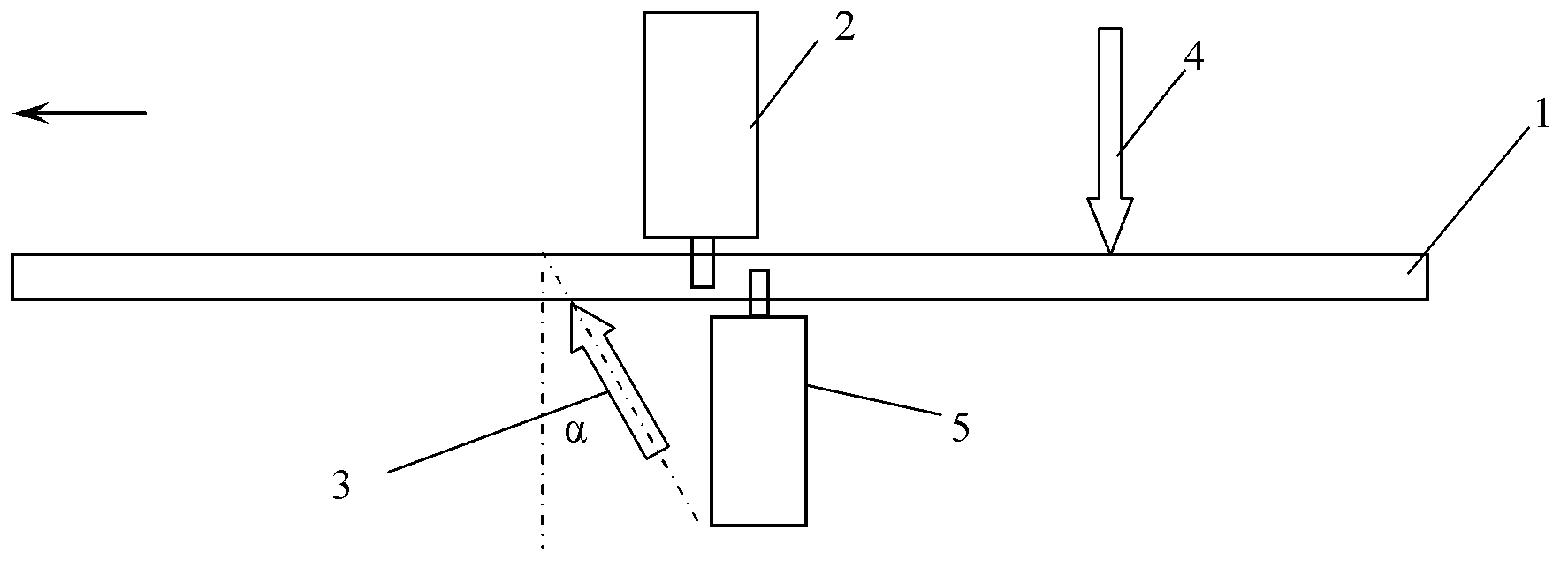
[0016] When the thickness of the stainless steel plate 1 to be welded is 30 mm, the first laser beam 3, the first friction stirring head 2, the second friction stirring head 5, and the second laser beam 4 are sequentially arranged along the direction opposite to the welding direction; The beam 3 and the second friction stirring head 5 are arranged on the back of the stainless steel plate, and the second laser beam 4 and the first friction stirring head 2 are arranged on the front of the stainless steel plate; the first laser beam 3 originates from a CO2 laser, and the first laser beam The angle between the centerline of the beam 3 and the vertical direction on the surface of the stainless steel plate is α=15°, the laser power of the first laser beam is P1=1200w, and the focal point of the first laser beam is adjusted relative to the surface of the stainless steel plate to be welded The position that makes the diameter of the laser spot radiated on the stainless steel plate to b...
Embodiment ( 2
[0018]When the thickness of the stainless steel plate 1 to be welded is 40 mm, the first laser beam 3, the first friction stirring head 2, the second friction stirring head 5, and the second laser beam 4 are sequentially arranged along the direction opposite to the welding direction; A laser beam 3 originates from a CO2 laser, the angle between the center line of the first laser beam 3 and the vertical direction on the surface of the stainless steel plate is α=30°, and the laser power of the first laser beam is P1=1600w, Adjust the position of the focus of the laser beam relative to the surface of the stainless steel plate to be welded so that the diameter of the laser spot radiated on the workpiece to be welded is 5mm; the second laser beam 4 originates from a CO2 laser, and the center of the second laser beam The line is perpendicular to the surface of the stainless steel plate, the laser power of the second laser beam is P2=4500w; the first friction stirring head is arranged...
Embodiment ( 3
[0020] When the thickness of the stainless steel plate 1 to be welded is 50 mm, the first laser beam 3, the first friction stirring head 2, the second friction stirring head 5, and the second laser beam 4 are sequentially arranged along the direction opposite to the welding direction; Laser beam 3 originates from CO2 laser, the angle between the center line of the first laser beam 3 and the vertical direction on the surface of the stainless steel plate is α=22 °, and the laser power of the first laser beam is P1=2000w, adjusted The position of the focus of the laser beam relative to the surface of the stainless steel plate to be welded makes the diameter of the laser spot radiated on the workpiece to be welded at 3mm; the second laser beam 4 originates from a CO2 laser, and the center line of the second laser beam Vertical to the surface of the stainless steel plate, the laser power of the second laser beam is P2=6000w; the first friction stirring head is arranged on the front ...
PUM
| Property | Measurement | Unit |
|---|---|---|
| Thickness | aaaaa | aaaaa |
| Diameter size | aaaaa | aaaaa |
| Thickness | aaaaa | aaaaa |
Abstract
Description
Claims
Application Information
 - R&D
- Intellectual Property
- Life Sciences
- Materials
- Tech Scout
- Unparalleled Data Quality
- Higher Quality Content
- 60% Fewer Hallucinations
Browse by: Latest US Patents, China's latest patents, Technical Efficacy Thesaurus, Application Domain, Technology Topic, Popular Technical Reports.
© 2025 PatSnap. All rights reserved.Legal|Privacy policy|Modern Slavery Act Transparency Statement|Sitemap|About US| Contact US: help@patsnap.com