Digital peak clipping method and digital peak clipping device
A digital and coefficient technology, which is applied in the field of digital peak clipping methods and devices, can solve the problems of ineffective reduction of PAPR, increased probability of peak miss cancellation, peak miss cancellation, etc., to reduce the probability of peak miss cancellation, eliminate peak, The effect of reducing PAPR
- Summary
- Abstract
- Description
- Claims
- Application Information
AI Technical Summary
Problems solved by technology
Method used
Image

Examples
Embodiment 1
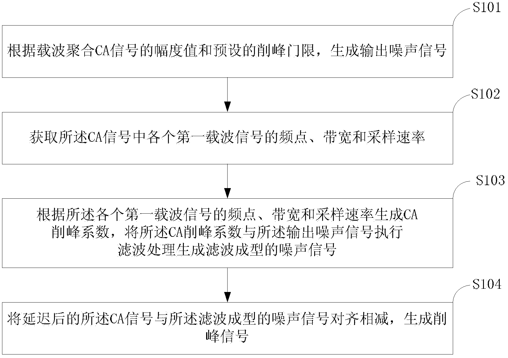
[0029] refer to figure 1 , figure 1 It is a flowchart of an embodiment of a digital peak clipping method provided in Embodiment 1 of the present invention; the digital peak clipping method includes:
[0030] S101: Generate an output noise signal according to the amplitude value of the carrier aggregation CA signal and a preset peak clipping threshold.
[0031] In this step, the amplitude value |x(n)| of the CA signal is compared with the preset peak clipping threshold A to obtain the output noise signal; the peak clipping threshold A is the maximum amplitude allowed by the clipping signal, which is determined by LTE-A The communication system is preset.
[0032] S102: Obtain frequency point, bandwidth and sampling rate of each first carrier signal in the CA signal.
[0033] In this step, the frequency point, bandwidth and sampling rate of each first carrier signal in the CA signal are obtained from the carrier aggregation configuration information of the CA signal.
[0034...
Embodiment 2
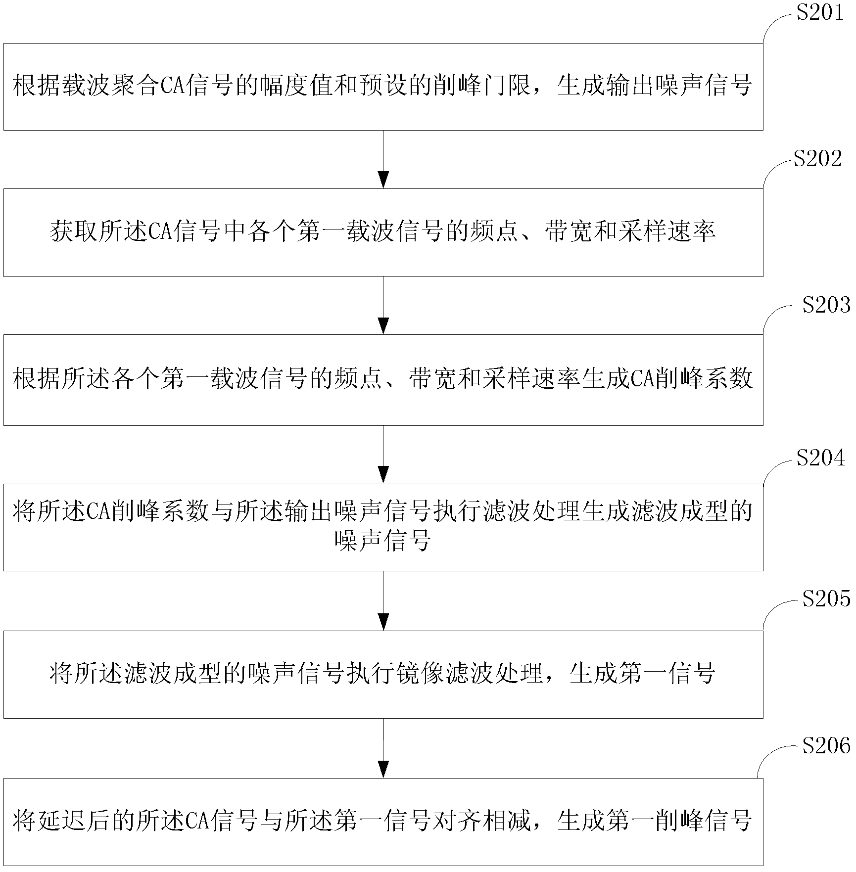
[0063] refer to figure 2 , figure 2 It is a flowchart of an embodiment of a digital peak-shaving method provided in Embodiment 2 of the present invention; the digital peak-shaving method includes:
[0064] S201: Generate an output noise signal according to the amplitude value of the carrier aggregation CA signal and a preset peak clipping threshold.
[0065] In practical applications, calculate the amplitude value |x(n)| corresponding to the CA signal x(n), compare the amplitude value |x(n)| of the CA signal with the preset peak clipping threshold A, and obtain the output noise signal noise(n);
[0066] Wherein, the calculation formula of the output noise signal noise(n) is as follows:
[0067] noise ( n ) = 0 , | x ( n ...
Embodiment 3
[0123] refer to Image 6 , Image 6 It is a schematic diagram of the first structure of a digital peak-shaving device embodiment provided in Embodiment 3 of the present invention; the digital peak-shaving device includes:
[0124] The output noise generation module 601 is configured to generate an output noise signal according to the amplitude value of the carrier aggregation CA signal and a preset peak clipping threshold.
[0125] The obtaining module 602 is configured to obtain the frequency point, bandwidth and sampling rate of each first carrier signal in the CA signal.
[0126] A noise shaping module 603, configured to generate a CA peak clipping coefficient according to the frequency point, bandwidth, and sampling rate of each first carrier signal, and perform filtering processing on the CA peak clipping coefficient and the output noise signal to generate filter-shaped noise Signal.
[0127] The peak clipping signal generating module 604 is configured to align and sub...
PUM
 Abstract
Description
Claims
Application Information
 - R&D
- Intellectual Property
- Life Sciences
- Materials
- Tech Scout
- Unparalleled Data Quality
- Higher Quality Content
- 60% Fewer Hallucinations
Browse by: Latest US Patents, China's latest patents, Technical Efficacy Thesaurus, Application Domain, Technology Topic, Popular Technical Reports.
© 2025 PatSnap. All rights reserved.Legal|Privacy policy|Modern Slavery Act Transparency Statement|Sitemap|About US| Contact US: help@patsnap.com