
Electromagnetic heating device with water-cooling heat dissipation function

An electromagnetic heating device, water cooling technology, applied in the direction of electric heating fuel, heating method, induction heating, etc., can solve the problems affecting the life of the coil, copper tube oxidation, poor thermal conductivity, etc., to achieve noise-free heat dissipation, good thermal conductivity , the effect of fast heat dissipation

Inactive Publication Date: 2013-03-27
陈梓平
View PDF1 Cites 2 Cited by
  • Summary
  • Abstract
  • Description
  • Claims
  • Application Information

AI Technical Summary

Problems solved by technology

[0003] The publication date is August 11, 1993, and the invention patent application with the publication number CN 1075198A discloses a water-cooled induction cooker. The induction cooker uses a hollow tube body coiled into an induction coil, and the hollow tube body and the external water tank And the cooling device is connected to form a water circulation to achieve heat dissipation and cooling. This application is suitable for high-power induction cookers and also uses water cooling for heat dissipation, but a cooling fan is still required for heat dissipation; in addition, when copper pipes are used as conduits for water conduction, it is easy to cause short circuits due to leakage; in addition , Copper tubes in contact with water for a long time will easily cause oxidation and corrosion, resulting in poor heat conduction and affecting the life of the reel

Method used


Image

  • Electromagnetic heating device with water-cooling heat dissipation function
  • Electromagnetic heating device with water-cooling heat dissipation function
  • Electromagnetic heating device with water-cooling heat dissipation function

Examples


Embodiment Construction

[0022] The present invention will be further described below in conjunction with the accompanying drawings and specific embodiments.

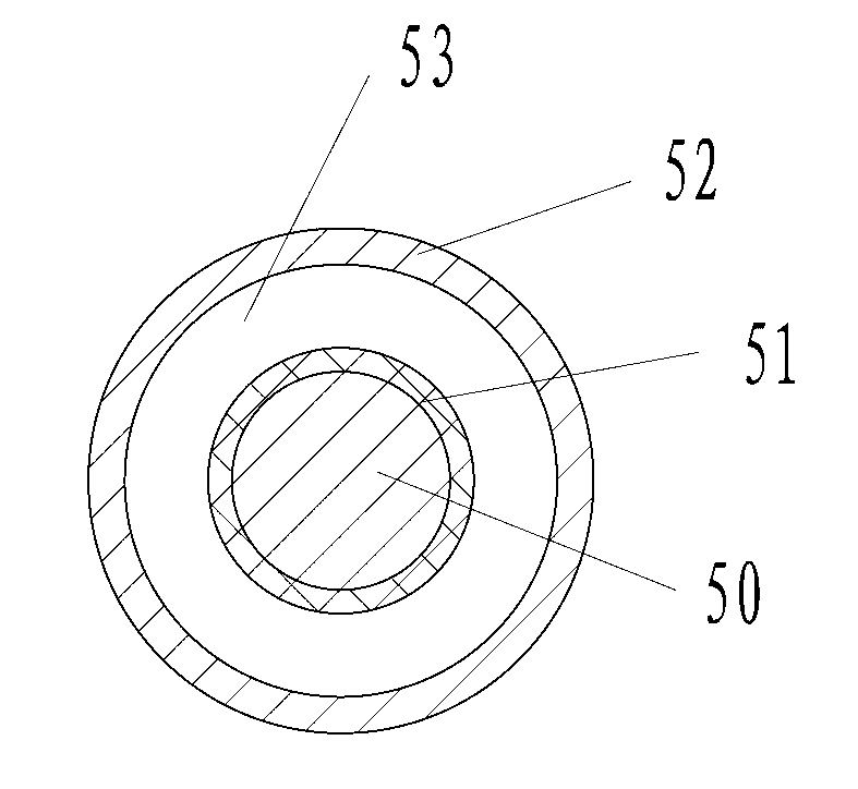
[0023] Such as figure 1 The shown wire with a water-cooled sleeve is composed of a metal wire 50 coated with an insulating layer 51 and then covered with a guide tube 52, wherein the guide tube 52 is a silicone tube, and the passage 53 between the guide tube 52 and the insulating layer 51 is Water circulation channel.

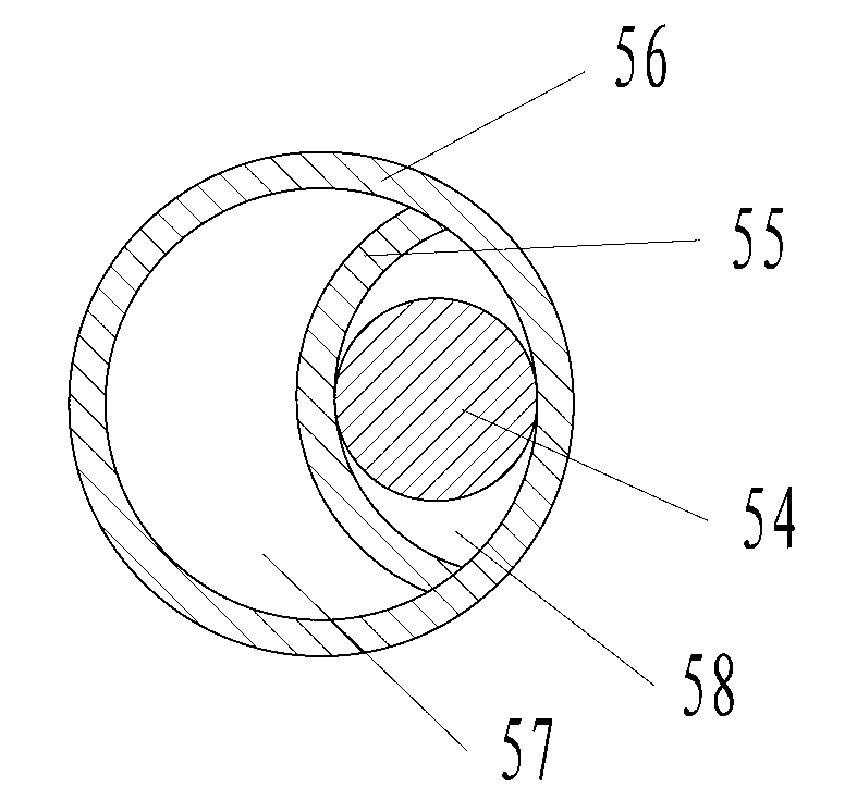
[0024] Such as figure 2 The shown wire with water-cooling casing is composed of a metal wire 54 and a diversion tube 56, wherein the diversion tube 56 is a silicone tube, and the interior of the diversion tube 56 is provided with the same quality as the diversion tube and integrated with the diversion tube. The partition wall 55 divides the interior of the draft tube into a first channel 57 and a second channel 58, wherein the metal wire 54 is arranged in the second channel 58, and the first channel 57 is a water circulation ...


PUM


Abstract

The invention relates to an electromagnetic heating device with a water-cooling heat dissipation function. The electromagnetic heating device comprises magnet exciting coils, a drive circuit and a control circuit, wherein the magnet exciting coils are used for generating an alternating magnetic field and are matched with cookware made of ferromagnetic materials to form electromagnetic vortexes so as to heat the cookware made of the ferromagnetic materials; and the drive circuit and the control circuit are used for controlling and driving the magnet exciting coils to work. The electromagnetic heating device is characterized in that the magnet exciting coils are wound by a lead with a water-cooling sleeve to form an integral structure, the lead with the water-cooling sleeve is formed by a metal wire wrapped with an insulating layer or a paint insulating layer, a diversion pipe is externally sleeved outside the metal wire wrapped with an insulating layer or a paint insulating layer, and the diversion pipe is communicated with a water circulation cooling control system to form a water circulation loop. The electromagnetic heating device is capable of directly cooling the magnet exciting coils by virtue of water circulation, and has the advantages of good heat dissipation effect, no noise, safety and durability, and the like.

Description

technical field [0001] The invention relates to a cooking utensil, in particular to a water-cooled and heat-dissipating electromagnetic heating device. Background technique [0002] As a high-efficiency and energy-saving electric heating appliance, the induction cooker has become an indispensable product in people's life. However, due to the high thermal efficiency of the induction cooker, the heating of the high-frequency induction heating coil and the control circuit is also very obvious. Most of the prior art uses cooling fans to dissipate heat and cool down to realize the safe operation of the induction cooker. The defect of short life, especially in the environment with high oil fumes for a long time, the cooling fan and electronic components are easy to stop working due to a large amount of oil, which affects the service life of the induction cooker. Especially, for high-power induction cooker (cooker), above-mentioned defect is particularly prominent. [0003] The p...

Claims


Application Information

Patent Timeline
IPC IPC(8): F24C7/00F24C7/06H05B6/42F24C15/00F24C7/08
Inventor 陈梓平
Owner 陈梓平
Learn More