
Emptying bin gate

A silo and valve technology, which is applied to the valve operation/release device, lift valve, valve details, etc., can solve the problems of inconvenient discharge of the silo and affect the production operation, and achieve the effect of labor-saving operation.

Inactive Publication Date: 2013-03-27
ZHENJIANG BAOCHENG GROUTING EQUIP
View PDF4 Cites 2 Cited by
  • Summary
  • Abstract
  • Description
  • Claims
  • Application Information

AI Technical Summary

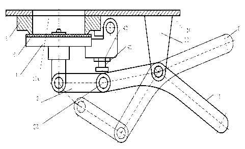
Problems solved by technology

[0002] The discharge bin of the existing mixer usually uses various valves for discharging. After long-term use, the slurry particles are easy to adhere and solidify in each activity link of the valve, which makes it inconvenient to discharge the discharge bin and seriously affects the production operation. Therefore, there is a need for a discharge bin door that is easy to open and close and will not be stuck by the slurry

Method used


Image

  • Emptying bin gate

Examples


Embodiment Construction

[0011] The present invention will be further described below in conjunction with the accompanying drawings and specific embodiments.

[0012] The discharge bin door is arranged at the bottom 10 of the discharge bin of the mixer, and specifically includes a valve plate 1, a connecting rod 2, an operating handle 3 and a limit fulcrum 4, and the bottom of the discharge bin is provided with a discharge port 10a, the limit The fulcrum 4 is set on one side of the discharge port 10a, the valve plate 1 is fixedly connected to one end of the connecting rod 2, and the surface of the valve plate 1 is opposite to the discharge port 10a, and the other end of the connecting rod 2 is connected to the operating handle 3 One end is hinged to form a hinge point 23, the hinge point 23 is in contact with the limit fulcrum 4, the middle part of the operating handle 3 is bent, the bending point 31 is hinged with the bracket 11 fixedly arranged at the bottom 10 of the discharge bin, and the connectin...


PUM


Abstract

The invention relates to the field of a stirrer, and in particular relates to an emptying bin gate. The emptying bin gate is arranged at the bottom of an emptying bin of a stirrer. The emptying bin gate comprises a movable gate valve plate, a connecting rod, an operating handle and a limiting fulcrum, wherein a discharge hole is arranged at the bottom of an emptying bin; the limiting fulcrum is arranged on one side of the discharge hole; the movable gate valve plate is fixedly connected with one end of the connecting rod, and a board of the movable gate valve plate faces to the discharge hole; the other end of the connecting rod is articulated with one end of the operating handle to form a hinge point; the hinge point is in contact connection with the limiting fulcrum; the middle part of the operating handle is articulated with the external bottom of the emptying bin; and one end at the hinge point on the central line of the connecting rod is higher than one corresponding end of the movable gate valve plate. The emptying bin gate disclosed by the invention realizes emptying without an existing valve, a rotation step has no contact with slurry, and thus no jamming is caused; the operating handle saves force in operation according to a lever principle; and the movable gate valve plate, the connecting rod, the operating handle and the limiting fulcrum form self locking when the emptying bin gate is closed, and no external force is needed.

Description

technical field [0001] The invention relates to the field of mixers, in particular to a discharge bin door. Background technique [0002] The discharge bin of the existing mixer usually uses various valves for discharging. After long-term use, the slurry particles are easy to adhere and solidify in each activity link of the valve, which makes it inconvenient to discharge the discharge bin and seriously affects the production operation. Therefore need a kind of discharge bin door that is easy to open and close and can not be stuck by slurry. Contents of the invention [0003] The purpose of the present invention is to solve the above-mentioned problems existing in the discharge bin of the existing mixer, and to provide a discharge bin door that is easy to open and close and will not be stuck by the slurry, which is specifically realized by the following technical solutions. [0004] A discharge bin door, which is arranged at the bottom of the discharge bin of the mixer, th...

Claims


Application Information

Patent Timeline
Patent Type & Authority Applications(China)
IPC IPC(8): F16K1/20F16K1/42F16K1/46F16K31/60
Inventor 哈寿伯徐刚陈燕
Owner ZHENJIANG BAOCHENG GROUTING EQUIP
Learn More