


Quick Research
Generate reliable direction feasibility study reports for your R&D in just a few steps.

Technical Q&A
Discover and master advanced knowledge NOW. Basics, ideas, possibilities, all at once.

Find Solutions
As an expert in R&D theories, this can generate solutions to your technical problems instantly.

Evaluate Feasibility
Analyze your overall solution with one click, know your potential R&D risks in advance.

Monitor Landscape
Get weekly tech updates, stay abreast of the latest tech innovations and key insights.
Power generation device
A technology for generating devices and power, applied in safety devices, steam engine devices, engine components, etc., can solve problems such as contact and bearing damage, and achieve the effect of avoiding bad conditions
- Summary
- Abstract
- Description
- Claims
- Application Information
AI Technical Summary
Problems solved by technology
Method used
Image

Examples
no. 1 Embodiment approach )
[0042] figure 1 The structure of the power generator 1 which is the 1st Embodiment of the power generator of this invention is shown. The power generation device 1 is a Rankine cycle heat engine including a circulation flow path 6 including an evaporator 2 , a screw expander 3 , a condenser 4 , and a working medium pump 5 . A working medium (for example, a Freon-based heat medium such as R245fa) is sealed in the circulation flow path 6 .
[0043] The evaporator 2 is a heat exchanger for exchanging heat between a heating medium supplied from a heat source outside the device (for example, steam extracted from a pit or steam produced by a boiler) and a working medium to evaporate the working medium. The working medium evaporated in the evaporator 2 is introduced into the screw expander 3 through the circulation flow path 6 . In the screw expander 3 , a screw rotor (not shown) is driven to rotate by the expansion of the working medium. The operating medium discharged in a stat...
no. 2 Embodiment approach )
[0065] Figure 4 A power generator 1a as a second embodiment of the power generator of the present invention is shown. In addition, in the description of the following embodiments, the same reference numerals are assigned to the same components as those of the above-described embodiments, and overlapping descriptions will be omitted.
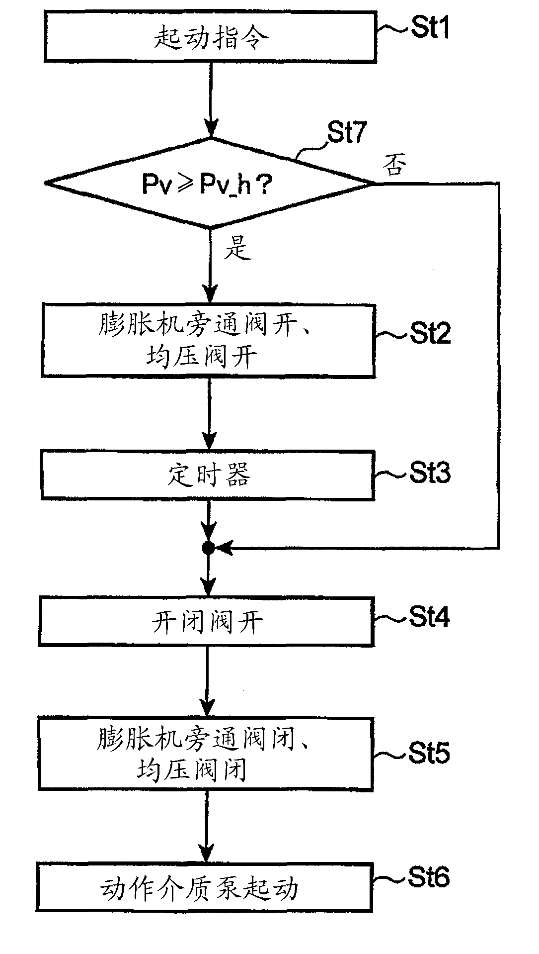
[0066] In addition to the configuration of the power generating device 1 of the first embodiment, the power generating device 1 a of the second embodiment further includes a pressure sensor (evaporating pressure sensor) 21 provided in the flow path 6 a between the evaporator 2 and the on-off valve 15 . There is one difference, and other points have the same configuration as the above-mentioned power generating device 1 . The evaporation pressure sensor 21 is a member that detects the pressure of the working medium downstream of the evaporator 2 in the circulation flow path 6 , and the evaporation pressure in the evaporator 2 can be detected by ...
no. 3 Embodiment approach )
[0075] Figure 7 A power generation device 1b that is a third embodiment of the power generation device of the present invention is shown.
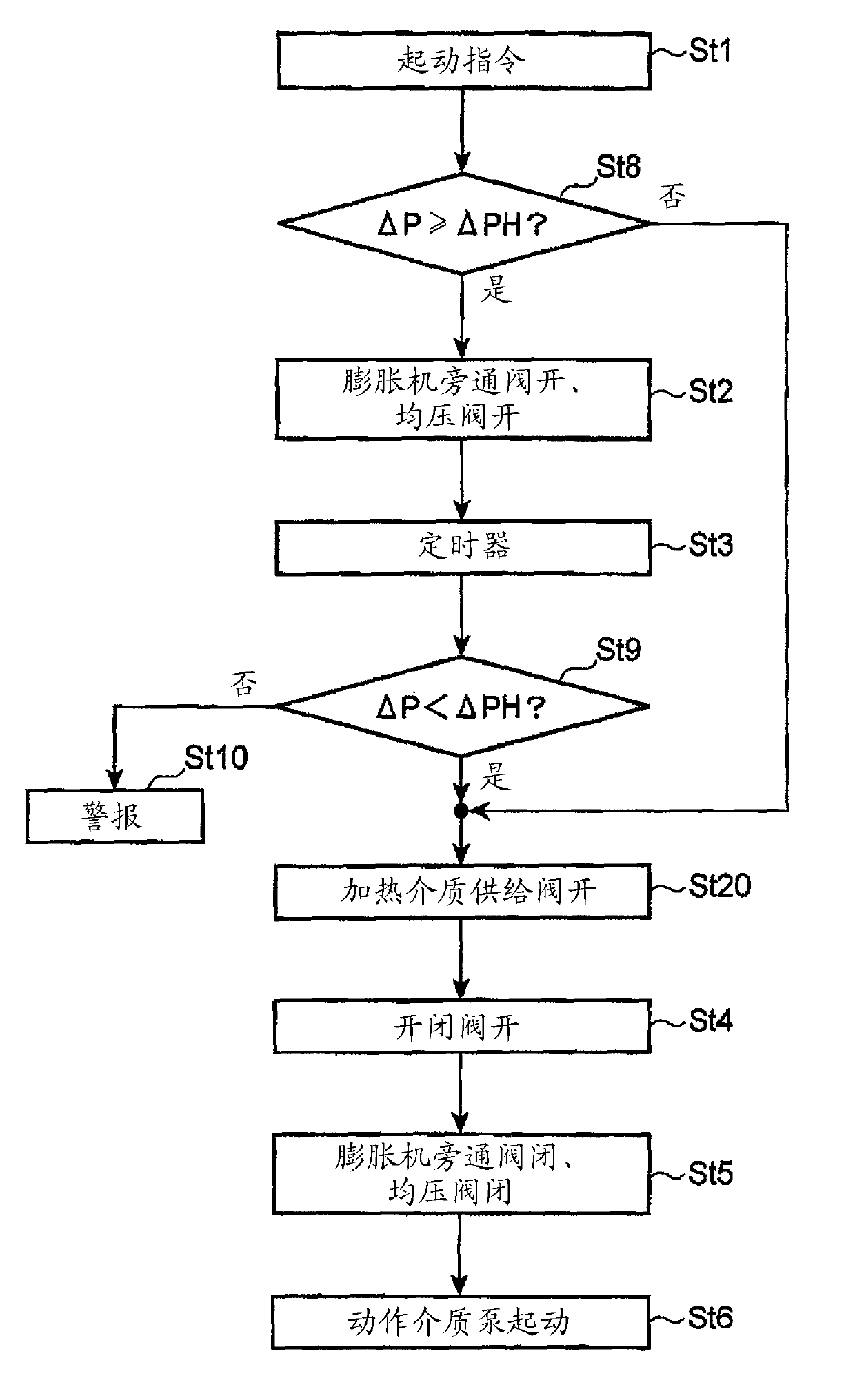
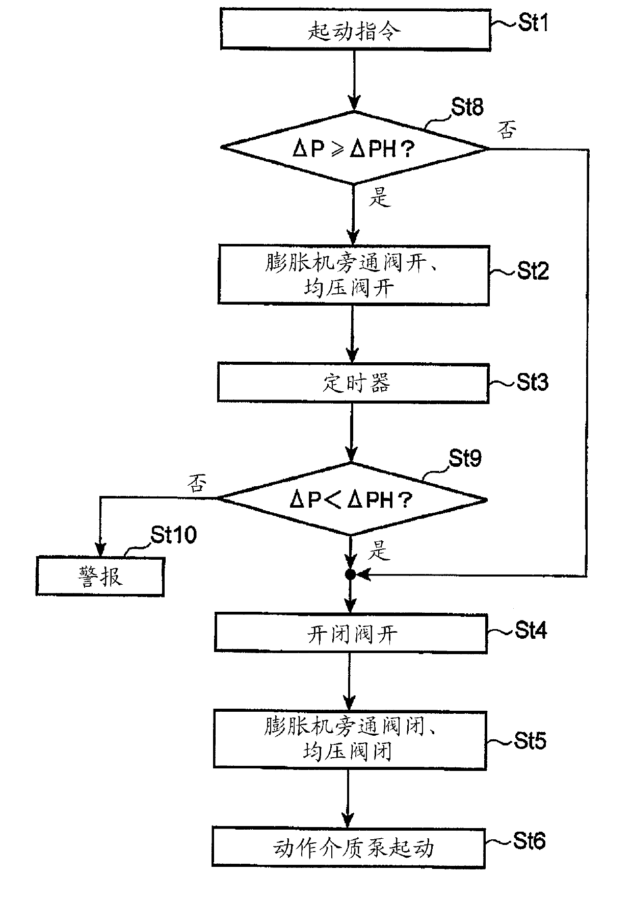
[0076] The power generator 1b of the third embodiment has the same structure as the power generator 1a of the second embodiment in many respects, but it is different from the second embodiment in that a discharge pressure sensor 22 is provided in addition to the structure of the power generator 1a described above. different. The discharge pressure sensor 22 is provided in the flow path 6 b between the expander 3 and the condenser 4 in the circulation flow path 6 .
[0077] The calculation unit 20b of the controller 20 is configured as described later so that the pressure difference ΔP between the pressure Pv detected by the evaporation pressure sensor 21 and the pressure Pd detected by the discharge pressure sensor 22 becomes a predetermined value when the operation is stopped. When the value ΔPH is greater than or equal to ΔPH, the pre...
PUM
 Abstract
Description
Claims
Application Information
 - R&D Engineer
- R&D Manager
- IP Professional
- Industry Leading Data Capabilities
- Powerful AI technology
- Patent DNA Extraction
Browse by: Latest US Patents, China's latest patents, Technical Efficacy Thesaurus, Application Domain, Technology Topic, Popular Technical Reports.
© 2024 PatSnap. All rights reserved.Legal|Privacy policy|Modern Slavery Act Transparency Statement|Sitemap|About US| Contact US: help@patsnap.com