Tensile force detecting device for conveyer belt

A detection device and tension force technology, applied in the direction of conveyor control devices, conveyors, conveyor objects, etc., can solve problems such as inability to make adjustments

Inactive Publication Date: 2013-03-27
昆山特力伯传动科技有限公司
View PDF4 Cites 23 Cited by
  • Summary
  • Abstract
  • Description
  • Claims
  • Application Information

AI Technical Summary

Problems solved by technology

However, the existing tensioning device cannot be adjusted in real time according to the actual situation

Method used


Image

  • Tensile force detecting device for conveyer belt
  • Tensile force detecting device for conveyer belt

Examples


Embodiment Construction

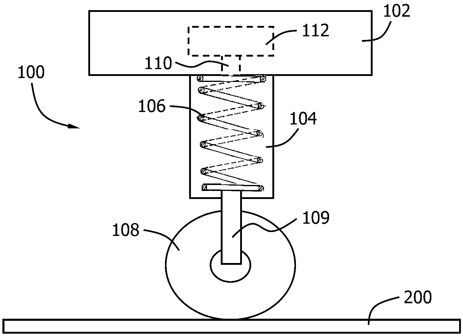
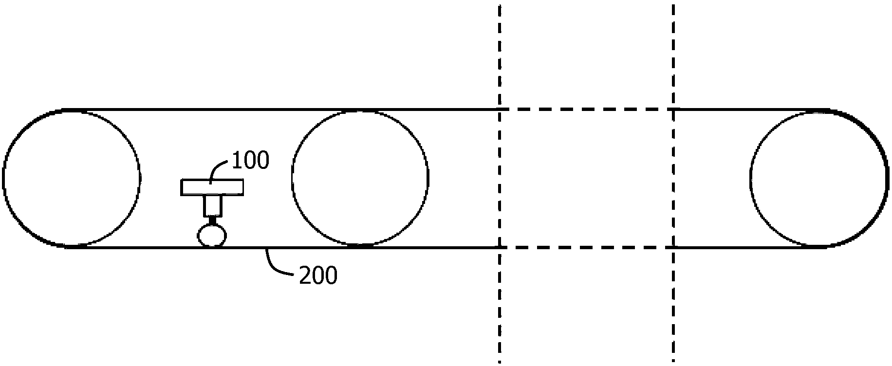
[0015] refer to figure 1 as shown, figure 1 A structural diagram of a tension detection device for a conveyor belt according to an embodiment of the present invention is disclosed. As shown in the figure, the conveyor belt tension detection device 100 includes a base 102 , a pipe 104 , a spring 106 , a pulley 108 , a connecting block 110 and a pressure sensor 112 . A base 102 is provided between the upper and lower sides of the conveyor belt, and the base 102 is hollow. The pipe 104 is connected to the base 102 , and the pipe 104 is arranged vertically. The pipe 104 is also hollow and the inside of the pipe 104 communicates with the inside of the base 102 . A spring 106 is placed in the tube 102 . The pulley 108 is mounted on the first end of the spring 106 through a pulley bracket 109 , and the first end is the lower end of the spring 106 . The rotating shaft of the pulley 106 is installed on the pulley bracket 109, and the pulley 108 bears against the inner surface of th...


PUM


Abstract

The invention discloses a tensile force detecting device for a conveyer belt. The tensile force detecting device comprises a chassis, a pipe, a spring, a pulley, a connecting block and a pressure sensor, wherein the chassis is hollowed and is arranged between the upper side and the lower side of the conveyer belt; the pipe is connected with the chassis, is hollowed and is arranged along a vertical direction; the spring is placed in the pipe; the pulley is arranged at a first end of the spring through a pulley support; a rotating shaft of the pulley is arranged on the pulley support; the pulley is held out against the inner surface of the conveyer belt which moves towards the lower side; the connecting block is arranged at a second end of the spring; the connecting block is placed in the chassis; the pressure sensor is placed in the chassis and is in contact with the connecting block; and the pressure applied by the connecting block to the pressure sensor can be detected by the pressure sensor. According to the tensile force detecting device for the conveyer belt, the real-time tensile force of the conveyer belt is detected through the spring and the pulley; the tensile force is collected from the lower side of the conveyer belt so as to remove the interference caused by the materials borne by the conveyer belt; and the spring ensures that the pulley can be clung to the conveyer belt all the time, so that accurate tensile force can be acquired.

Description

technical field [0001] The invention relates to the field of conveyor belts, in particular to a tension detection device for conveyor belts. Background technique [0002] Conveyor belt, also known as belt conveyor, is an ideal high-efficiency continuous transportation equipment, especially suitable for continuous transportation of bulk and powdery materials. Compared with other transportation equipment (such as locomotives), the belt conveyor has the advantages of long transportation distance, large transportation capacity, continuous transportation, etc., and it is reliable in operation and easy to realize automation and centralized control. [0003] Belt conveyors generally include the following main components: conveyor belts, drive rollers, tensioning devices, braking devices and cleaning devices. [0004] The conveyor belt is in the form of a ring, which is set on the driving roller and driven by the driving roller to realize the function of conveying. Commonly used c...

Claims


Application Information

Patent Timeline
Patent Type & Authority Applications(China)
IPC IPC(8): B65G43/02B65G43/04B65G23/44
Inventor 朱井钟
Owner 昆山特力伯传动科技有限公司
Why Eureka
Try Eureka