Electric power steering apparatus
a technology of electric power steering and electric motor, which is applied in mechanical devices, transportation and packaging, and gearing, etc., can solve the problems of belt vibration and noise, and achieve the effect of reducing vibration and nois
- Summary
- Abstract
- Description
- Claims
- Application Information
AI Technical Summary
Benefits of technology
Problems solved by technology
Method used
Image
Examples
first embodiment
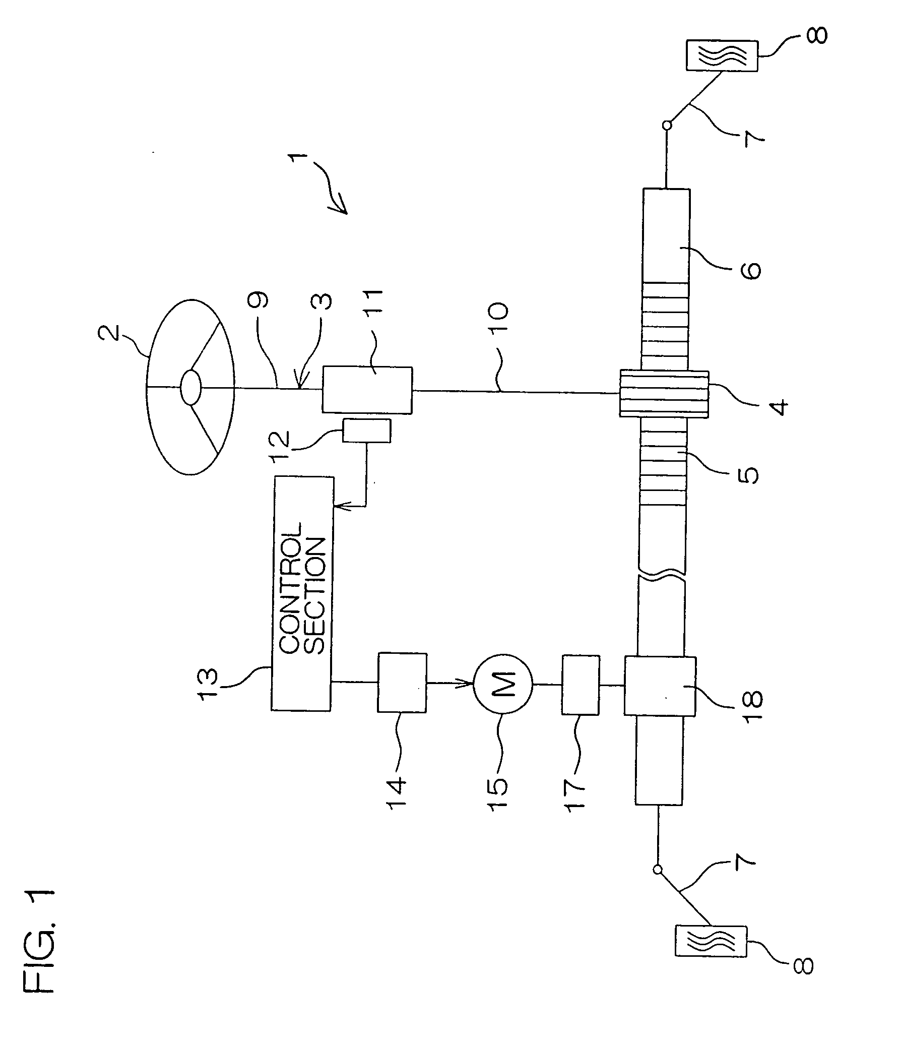
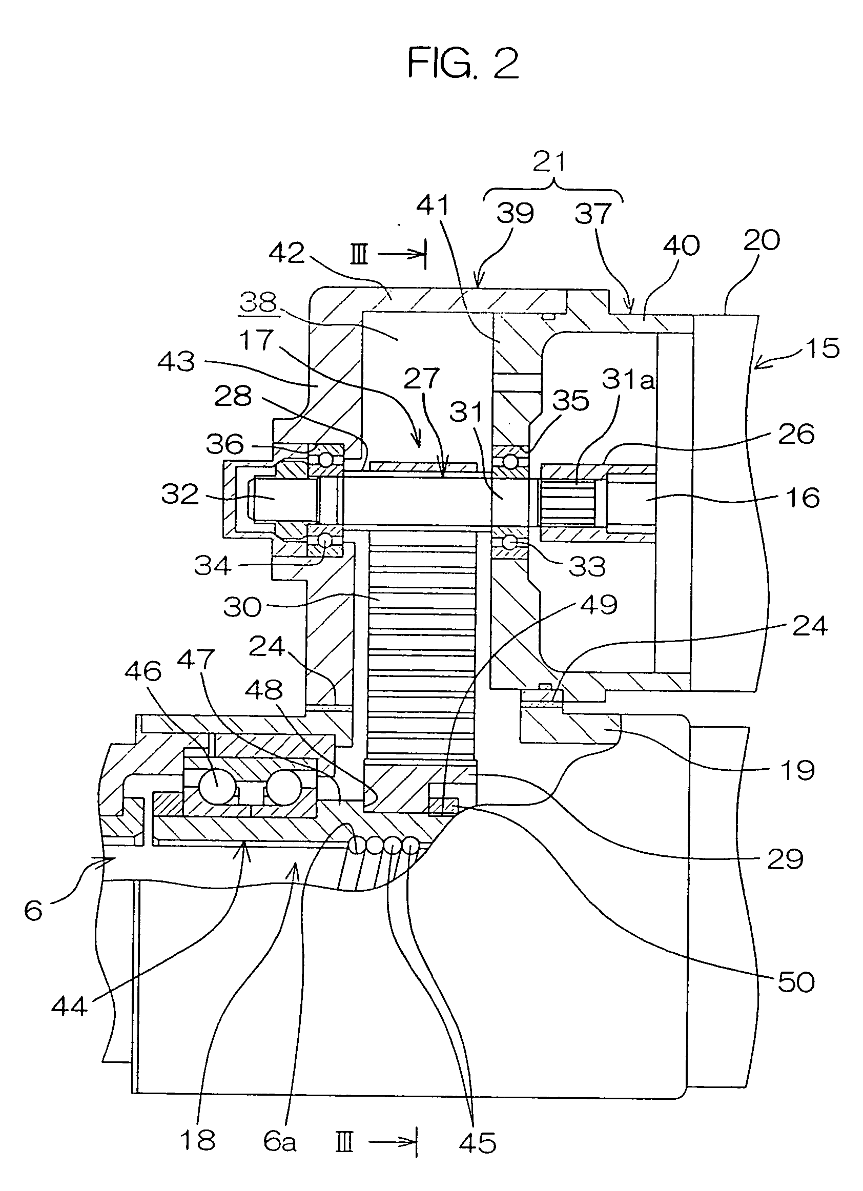
[0032]FIG. 1 is a schematic view showing the schematic configuration of an electric power steering apparatus according to a first embodiment of the present invention. Referring to FIG. 1, an electric power steering apparatus (EPS) 1 comprises a steering shaft 3 connected to a steering wheel 2 serving as a steering member, and a rack shaft 6 serving as a steering shaft having a pinion gear 4 provided at a front end of the steering shaft 3 and a rack gear 5 engaging with the pinion gear 4 and extending toward the right and left sides of a vehicle.
[0033] Tie rods 7 are respectively coupled to both ends of the rack shaft 6. Each of the tie rods 7 is connected to a corresponding wheel 8 through a corresponding knuckle arm (not shown) When the steering wheel 2 is operated so that the steering shaft 3 is rotated, the rotation is converted into the linear motion of the rack shaft 6 along the right and left sides of the vehicle by the pinion gear 4 and the rack gear 5. Consequently, the rol...
second embodiment
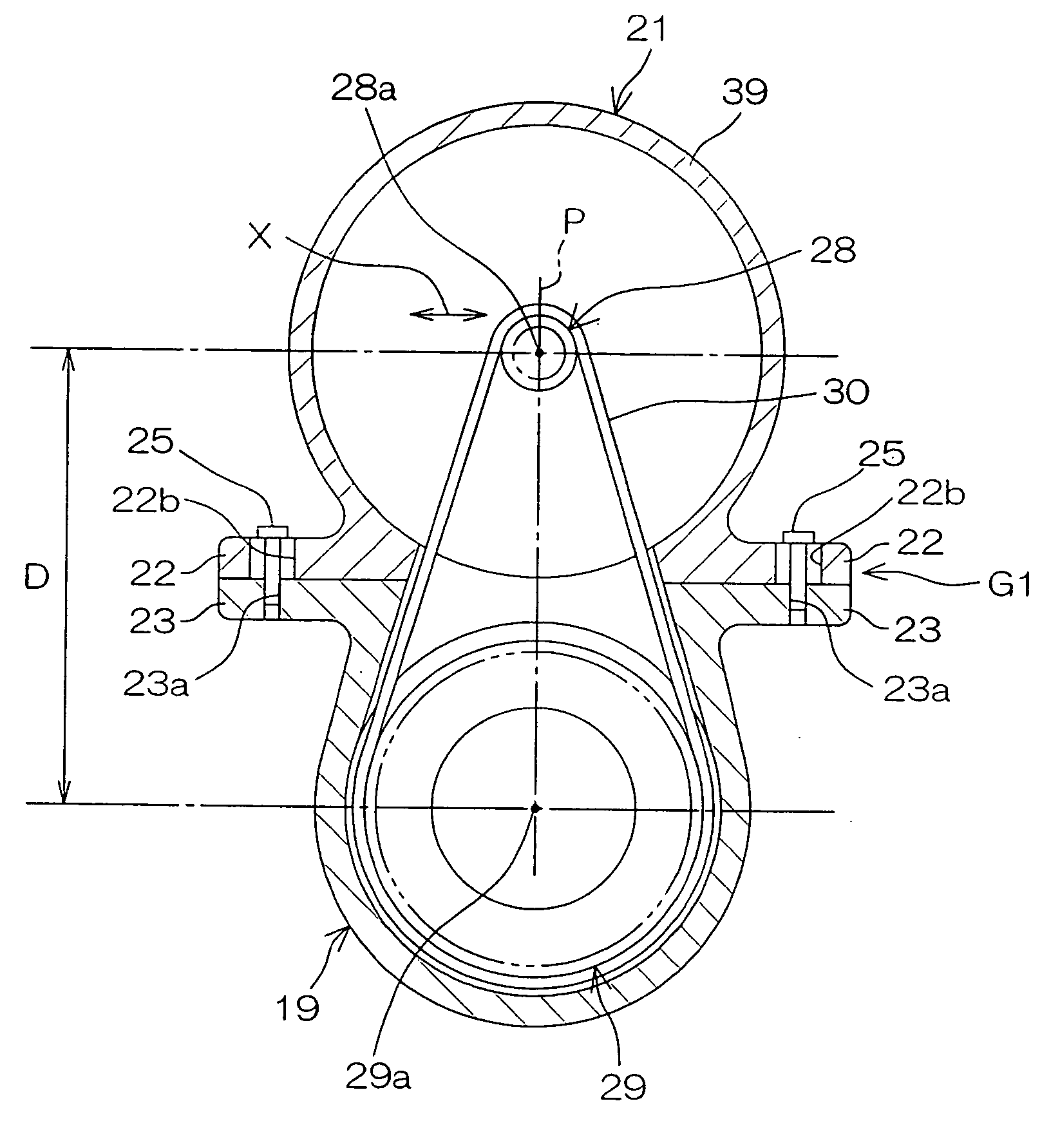
[0049] Then, FIG. 4 illustrates a second embodiment of the present invention. Referring to FIG. 4, the present embodiment differs from the first embodiment shown in FIG. 3 in that the spacer 24 is abandoned, and a first housing 21 for holding an input pulley 28 and a rack housing 19 serving as a second housing for holding an output pulley 29 through a bearing 46 and a rack shaft 6 are relatively slid in a lateral direction X along their mounting flanges 22 and 23 to adjust a center-to-center distance D between respective center axes 28a and 29a of the input and output pulleys 23a and 29a. The lateral direction X is a direction approximately perpendicular to a plane P including the center axes 28a and 29a.
[0050] In order to allow the foregoing, a screw insertion hole 22b of the mounting flange 22 is formed into a slot along the lateral direction X, to guide the relative slide between both the housings 19 and 21 in the lateral direction X through the screw insertion hole 22b composed...
third embodiment
[0052] Then, FIG. 5 illustrates a third embodiment of the present invention. Referring to FIG. 5, the third embodiment differs from the second embodiment shown in FIG. 4 in that both the housings 21 and 19 are relatively slid along a lateral direction X in the second embodiment shown in FIG. 4, while a rack housing 19 and a connection housing 37A are relatively slid along a longitudinal direction Y to adjust a center-to-center distance D, and there is provided a single drive screw 51 for relatively sliding the rack housing 19 and the connection housing 37A along the longitudinal direction Y in the present embodiment. The longitudinal direction Y is a direction approximately perpendicular to both a center axis 28a and a center axis 29a.
[0053] Specifically, there is provided a guided section 52 composed of an outward annular flange in a peripheral wall 40 of the connection housing 37A, and there is provided an extended section 53 extending parallel to an input shaft 27 from an end wa...
PUM
 Abstract
Description
Claims
Application Information
 - R&D
- Intellectual Property
- Life Sciences
- Materials
- Tech Scout
- Unparalleled Data Quality
- Higher Quality Content
- 60% Fewer Hallucinations
Browse by: Latest US Patents, China's latest patents, Technical Efficacy Thesaurus, Application Domain, Technology Topic, Popular Technical Reports.
© 2025 PatSnap. All rights reserved.Legal|Privacy policy|Modern Slavery Act Transparency Statement|Sitemap|About US| Contact US: help@patsnap.com


