
Low-cost balancing signal passive element

A technology of passive components and balanced signals, which is applied in the direction of electrical components, impedance networks, multi-terminal pair networks, etc., can solve the problems of signal asymmetry of positive and negative signal lines, large installation space, high cost, etc., and achieve strong promotion effect and economic benefits. Small signal distortion, simple effect

Inactive Publication Date: 2013-03-20
BIZLINK ELECTRONICS KUNSHAN CO LTD
View PDF4 Cites 0 Cited by
  • Summary
  • Abstract
  • Description
  • Claims
  • Application Information

AI Technical Summary

Problems solved by technology

First, this type of passive equalizer consists of a frequency selection network composed of multiple passive components and is integrated in the chip. The manufacturing process is relatively complicated and the cost is high; It is impossible to make the components exactly the same, and there must be certain errors, which will cause signal asymmetry on the positive and negative signal lines, thereby affecting the accuracy of signal transmission; third, the volume of such passive equalizers is usually relatively small. Larger, which requires a larger installation space, but as electronic products become increasingly miniaturized, a large passive equalizer is obviously not practical; fourth, it is necessary to interrupt the differential pair itself, and then connect it to the break. equalizer, which will cause inconvenience for users in application, and a dedicated line must be specially designed for adding this passive equalizer

Method used


Image

  • Low-cost balancing signal passive element
  • Low-cost balancing signal passive element
  • Low-cost balancing signal passive element

Examples


Embodiment 1

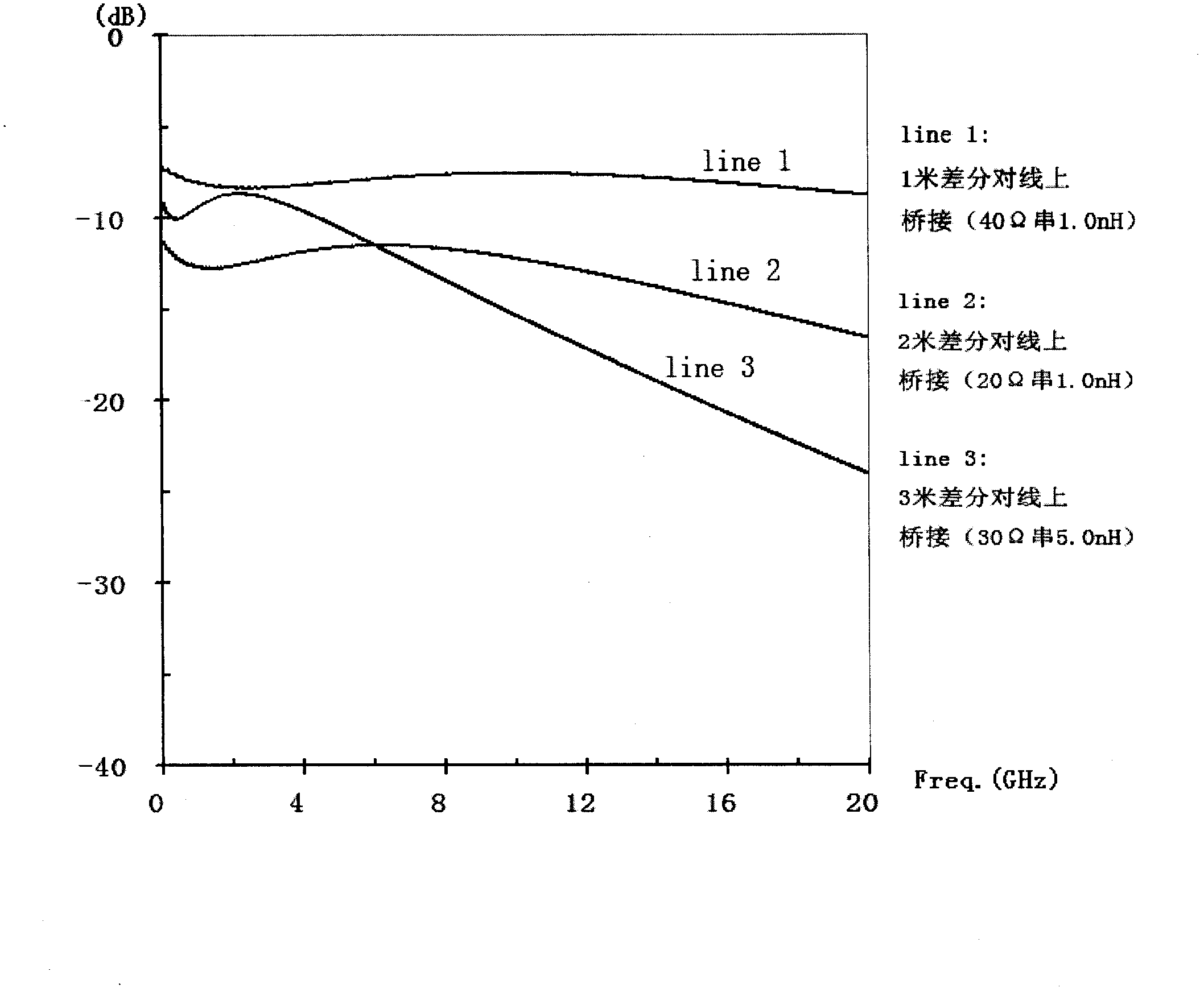
[0026] Embodiment 1. Connect the two ends of the passive element composed of a resistance of 40Ω and an inductance of 1.0nH in series with two signal lines of a 1-meter-long differential pair line respectively, that is, the passive element is bridged to the differential pair line, and the signal passes through this The change in frequency response for differential pairs is as follows: Figure 4 Shown in line 1. When the signal frequency is 0Hz, the signal attenuation is -6.9dB; when the signal frequency is 10GHz, the signal attenuation is -7.6dB; when the signal frequency is 20GHz, the signal attenuation is -8.8dB. The experimental results show that when the signal frequency is between 0Hz and 20GHz, if a passive component composed of a 40Ω resistor and a 1.0nH inductance is bridged on the two signal lines of a 1-meter-long differential pair, the differential The signal on the line can maintain a relatively stable attenuation trend.

Embodiment 2

[0027] Embodiment 2. Connect the two ends of the passive element composed of a resistance of 20Ω and an inductance of 1.0nH in series with two signal lines of a 2-meter-long differential pair line respectively, that is, bridge the passive element on the differential pair line, and the signal passes through this The change in frequency response for differential pairs is as follows: Figure 4 Shown in line 2. When the signal frequency is 0Hz, the signal attenuation is -10.8dB; when the signal frequency is 5.2GHz, the signal attenuation is -11.6dB; when the signal frequency is 14GHz, the signal attenuation is -13.8dB. The experimental results show that when the signal frequency is between 0Hz and 14GHz, if a passive component composed of a 20Ω resistor and a 1.0nH inductance is connected in series on the two signal lines of a 2-meter-long differential pair, the differential The signal on the line can also maintain a relatively stable attenuation trend.

Embodiment 3

[0028] Embodiment 3. Connect the two ends of the passive element composed of a resistance of 30Ω and an inductance of 5.0nH in series with two signal lines of a 3-meter-long differential pair line respectively, that is, bridge the passive element on the differential pair line, and the signal passes through this The change in frequency response for differential pairs is as follows: Figure 4 Shown in line 3. When the signal frequency is 0Hz, the signal attenuation is -8.6dB; when the signal frequency is 1.9GHz, the signal attenuation is -8.7dB; when the signal frequency is 6GHz, the signal attenuation is -11.5dB. The experimental results show that when the signal frequency is between 0Hz and 6GHz, if a passive component composed of a 30Ω resistor and a 5.0nH inductance is connected in series on the two signal lines of a 3-meter-long differential pair, the differential The signal on the line can also maintain a relatively stable attenuation trend.

[0029] see Figure 5 , the...


PUM


Abstract

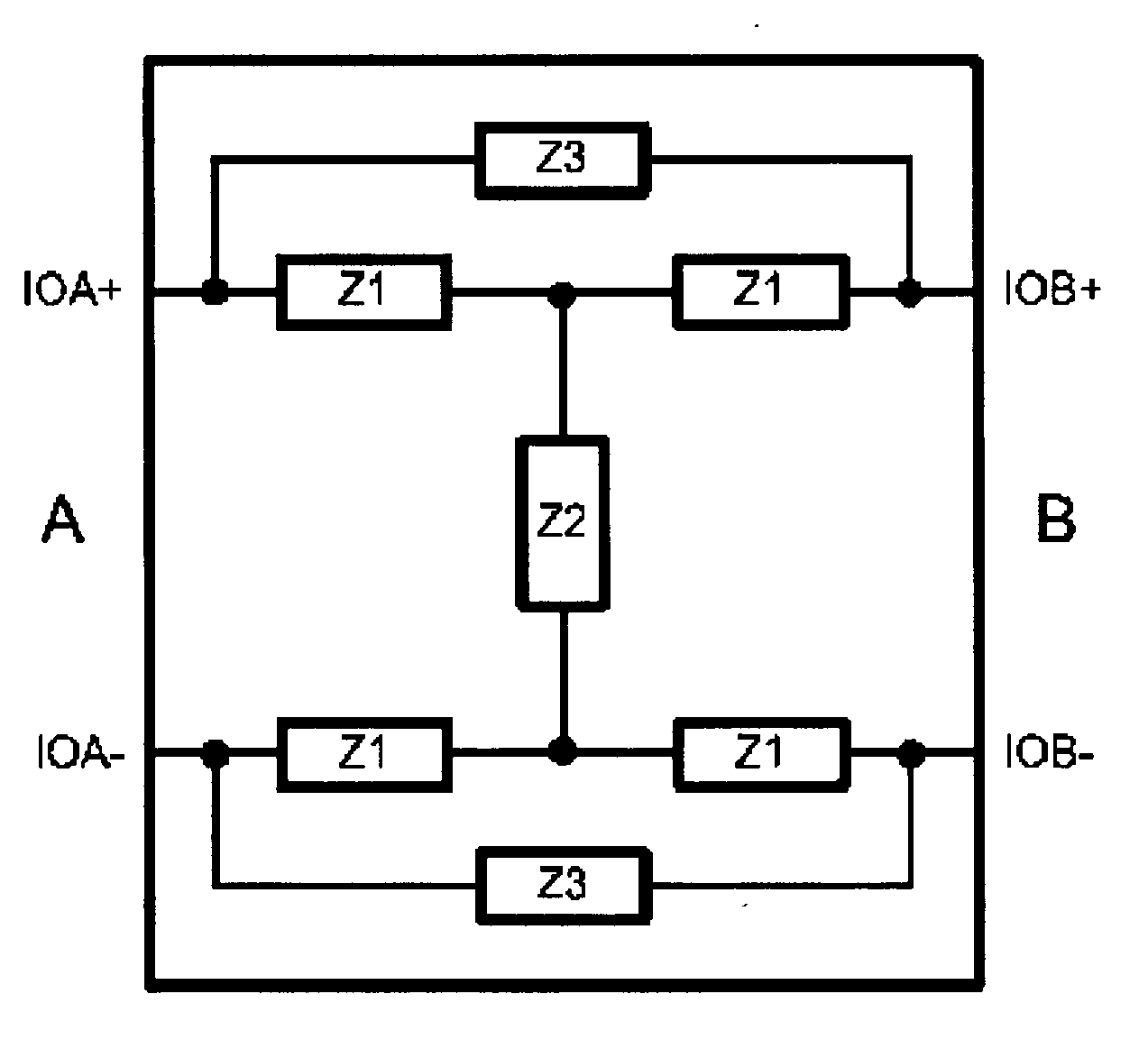
The invention relates to a passive element and discloses a low-cost balancing signal passive element. The low-cost balancing signal passive element comprises a resistor and an inductor, wherein a resistance value of the resistor is larger than 1 ohm, and the resistor and the inductor are connected in series and packaged in the same module. The low-cost balancing signal passive element has the advantages that the passive element can be connected on positive and negative signal lines of a differential pair line in a bridged mode to achieve balancing of high-speed differential signals and enable distortion of the signals transmitted by the differential pair line to be small to the greatest extent. A group of differential pair lines can achieve signal balance only by needing at least one passive element, and original lines are not needed to break, so that the cost of import design is very low, and the low-cost balancing signal passive element has good popularizing effect and economic benefit. In addition, the structure of the passive element is simple, the volume of a whole module can be very small, and the passive element can be installed in a small-volume device. Furthermore, the passive element is connected between the positive and negative signal lines of the differential pair line in a bridged mode and has equipotent and same influence on positive and negative signals, so that asymmetry of the positive and negative signals is not increased.

Description

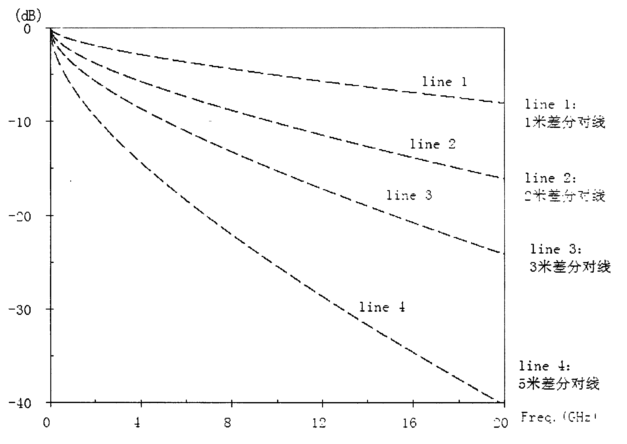
technical field [0001] The invention relates to a passive element, in particular to a low-cost balanced signal passive element. Background technique [0002] Currently, high-speed differential pairs are widely used, for example, in high-definition television and digital audio. When the signal is transmitted on the high-speed differential pair line, due to the attenuation characteristics of the line structure itself, the attenuation of the high-frequency signal is greater than that of the low-frequency signal, which will cause ISI (InterSymbol Interference, Intersymbol Interference), If the signal is unstable, the effective amplitude of the signal will be reduced, which will affect the receiving quality of the signal. Such as figure 1 As shown, as the length of the differential pair line increases and the signal frequency increases, the difference between high and low frequency attenuation will become more obvious, so the impact on the signal will be greater. [0003] In v...

Claims


Application Information

Patent Timeline
Patent Type & Authority Applications(China)
IPC IPC(8): H03H7/03
Inventor 谢金安
Owner BIZLINK ELECTRONICS KUNSHAN CO LTD
Learn More